5-3
TROUBLESHOOTING
SL 35-199, SL 45-260 MODULATING GAS BOILERS
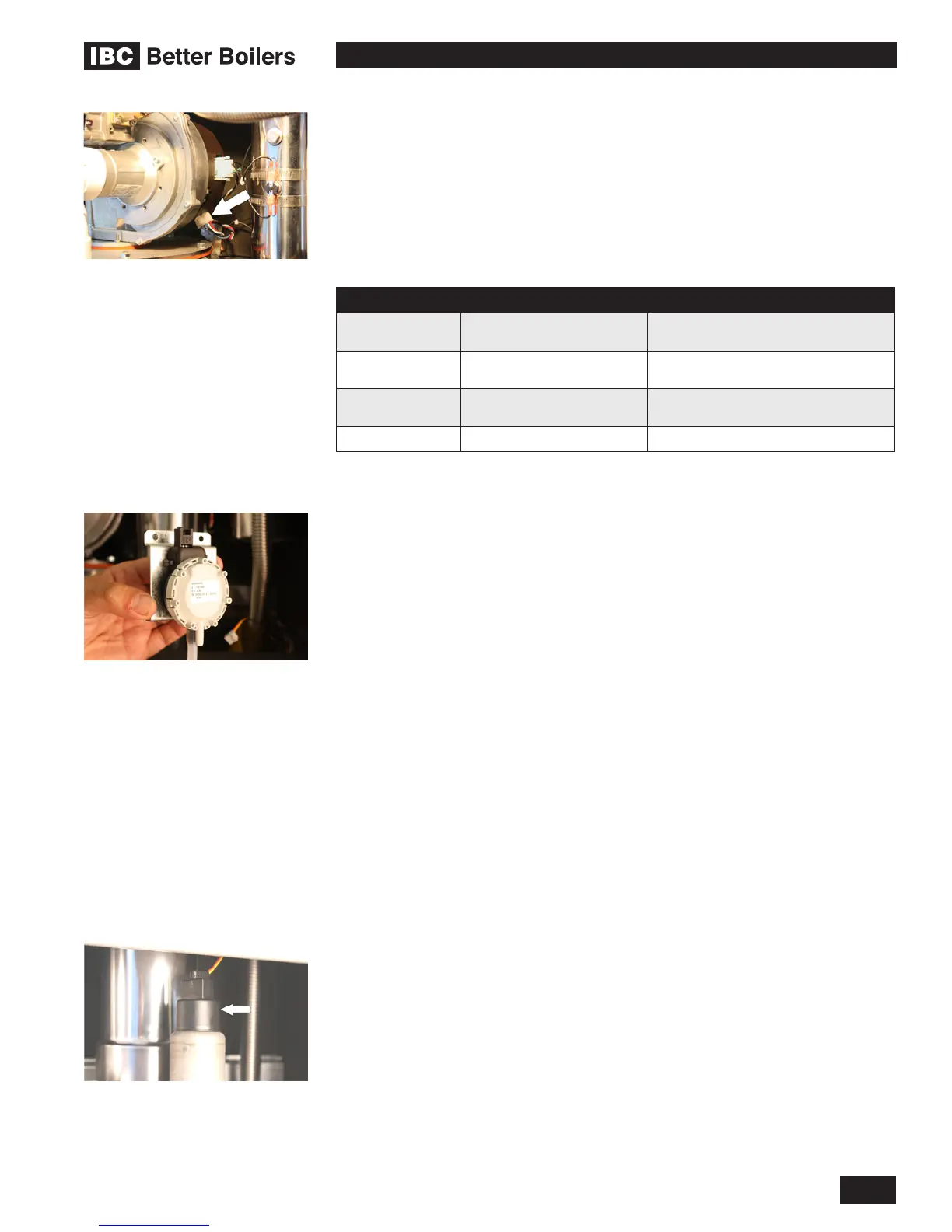
5.2.2 Fan/Blower
Operating power is provided by means of a separate 120 VAC connector at the
bottom of the fan (white/black/green). Control of the fan is provided via a four
lead connector at the top of the fan. This connector feeds a PWM control signal
(black wire) from the controller and provides a tachometer signal (white wire)
back from the fan. Unplugging the control connector will cause the fan to go to
high speed and trigger a “Blocked Vent Error” within 6 seconds if the boiler is
operating.
LEAD COLOR FUNCTION TROUBLESHOOTING
Red
35 VDC Positive power
terminal
Fan will only operate at max. speed if
disconnected.
Blue
35 VDC Negative power
terminal
Fan will only operate at max. speed if
disconnected.
Black Signal from controller
Fan will only operate at max. speed if
disconnected.
White Fan tach. 2 pulses/rev (freq x 30=rpm)
Table 10: Fan Operation
5.2.3 Differential Air Pressure Sensor
Do not blow into the ports of the sensor, this is not a switch and “does not
click when closed”. Excessive pressure will damage the sensor thus requiring
replacement. The sensor values are located in the advanced diagnostics section
of the controller. In general, the Fan Pressure and the Required Pressure
should be very close to each other while the boiler is in operation. If the required
pressure is higher than the actual pressure there are several possible causes.
• Exhaust and/or Air Intake piping installed longer that allowed
• Improper grading of the Exhaust and/or Air Intake piping allowing condensate
to be trapped in the piping
• Re-IngestionofuegasseshascausedtheVenturiand/orFanImpellerto
erode, becoming ineffective.
• Air Pressure Sensor tubing not correctly attached.
5.2.4 Water Pressure Sensor
The water pressure sensor ensures there is adequate pressure in the heating
system for safe operation. The pressure is displayed in PSI as the default. If the
systempressureshoulddropbelow8PSItheringrateoftheboilerisreduced.
Ifthepressuredropsto4PSIorlower,theboilerwillnotre.
Check operation of the sensor by isolating the boiler from its system piping,
closingthesystemllvalvethencrackingthepressurereliefvalve;thepressure
displayedshouldreectdecliningpressure.Ifitremains“xed”,drainboilerand
replace sensor, or dislodge any blocking debris from sensor inlet channel and
reinsert.
Control wire plug
Air pressure sensor. Do not blow
into sensor ports.
Water pressure sensor

 Loading...


