INSTALLATION AND OPERATION INSTRUCTIONS
5-2
SL 35-199, SL 45-260 MODULATING GAS BOILERS
This section details the method for troubleshooting the non-standard electronic
components on the boiler including the electronic differential air pressure sensor
and the temperature sensors.
5.2.1 Temperature Sensors
The resistance of the temperature sensors varies inversely with temperature. To
test, measure the temperature of the sensed environment and compare with the
value derived from the measurement of the resistance (obtained by connecting a
goodqualitytestmetercapableofmeasuringupto5,000kΩ(5,000,000Ω)atthe
controller end of the sensor lead).
To obtain a resistance reading, remove power to the boiler. For the supply water
and return water temperature sensors, remove the wire leads by disconnecting
their respective Molex connectors. Place multi-meter probes into sensor’s female
Molex connector socket. Do not apply voltage to the sensor (damage may result).
TEMPERATURE RESISTANCE TEMPERATURE RESISTANCE
°F °C Ω °F °C Ω
0 -18 85,362 100 38 5,828
5 -15 72,918 105 41 5,210
10 -12 62,465 110 43 4,665
15 -9 53,658 115 46 4,184
20 -7 42,218 120 49 3,760
25 -4 39,913 125 52 3,383
30 -1 34,558 130 54 3,050
35 2 29,996 135 57 2,754
40 4 26,099 140 60 2,490
45 7 22,763 145 63 2,255
50 10 19,900 150 66 2,045
55 13 17,436 155 68 1,857
60 16 15,311 160 71 1,689
65 18 13,474 165 74 1,538
70 21 11,883 170 77 1,403
75 24 10,501 175 79 1,281
80 27 9,299 180 82 1,172
85 29 8,250 185 85 1,073
90 32 7,334 190 88 983
95 35 6,532 195 91 903
Table 9: Temperature Sensor resistance values
5.2
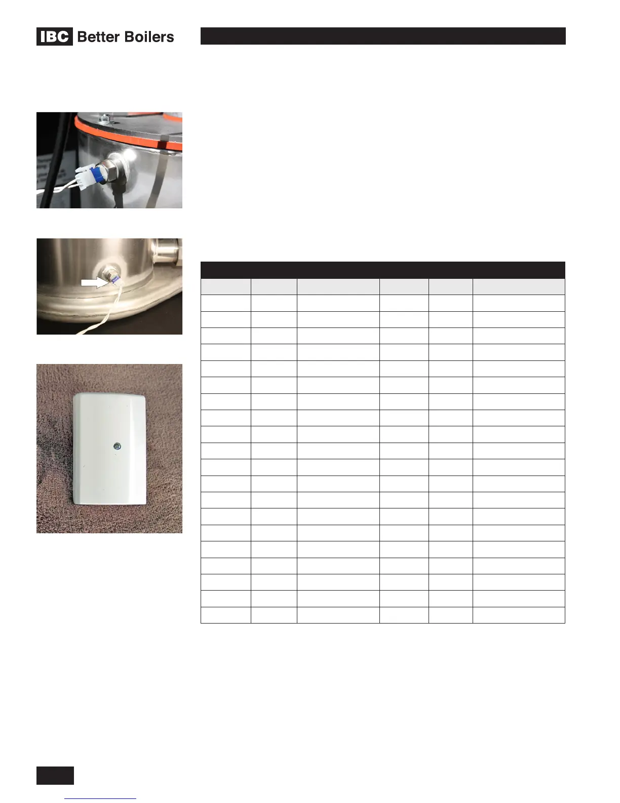
Supply water temperature sensor
Return water temperature sensor
IBC Outdoor Sensor
10KΩ Temperature sensors
supplied with boiler (above)
See table #9 for resistance values

 Loading...


