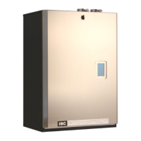
INSTALLATION AND OPERATION INSTRUCTIONS
1-22
SL 35-199, SL 45-260 MODULATING GAS BOILERS
WARNING
Do not use automotive-type
ethylene or other types of
automotive glycol antifreeze,
or undiluted antifreeze of
any kind. This may result
in severe boiler damage. It
is the responsibility of the
Installer to ensure that glycol
solutions are formulated to
inhibit corrosion in hydronic
heating systems of mixed
materials. Improper mixtures
and chemical additives may
cause damage to ferrous and
non-ferrous components as
well as non-metallic, wetted
components, normally found
in hydronic systems. Ethylene
glycol is toxic, and may be
prohibited for use by codes
applicable to your installation
location. For environmental
and toxicity reasons, IBC
recommends only using non-
toxic propylene glycol.
Propylene glycol solution is commonly used in a closed loop where freeze
protection is required. Its density is lower than that of water, resulting in
lowerthermalperformanceatagivenowandpressure.Asaruleofthumb,
a 50%:50% solution of propylene glycol and water will require an increased
system circulation rate (gpm up 10%), and system head (up 20%) to provide
performance equivalent to straight water.
Propylene Glycol mixtures of 25% (minimum) - 50% (maximum) are acceptable
for use with-in the boiler and piping system.
The SL series modulating boilers offer exceptional matching of heat generation to
radiation.Thelowminimumringisbettersuitedtolowthermalloadspresented
in a typical multi-zoned radiation system. However, where individual zones in
aheatingsystemhaveloadsunder10,000Btu/hr,thesystemwillstillbenet
through use of a buffer tank to ensure a controlled supply temperature, and to
prevent short cycling. Buffering should be added on the secondary piping of the
relevant load, to avoid bulking up the thermal mass of the primary piping circuit
(and potentially lengthen the duration of the transition from hot to cool loads).
SLmodulatingseriesboilerscanbeconnecteddirectlytoaoorofnon-oxygen
barrier polybutylene material (PB tubing). For maintenance of warranty on such
systems,werequireevidenceofathoroughushingofallloops,plusinstallation
ofadirtseparatororsidestreamlter.Aseparator/ltermaintenanceroutine
shallbecarriedoutaftertheretrot,withlterclearingafterthe1stday,1stweek,
month and annually thereafter. Care is to be taken to avoid use of ferrous
ttings and pumps on Non Oxygen Barrier tube systems.
1.6.2 Basic System Piping Arrangements
PRIMARY / SECONDARY PIPING - BENEFITS AND INSTALLATION RULES
1. Goodcirculatingwaterowthroughtheboilerirrespectiveofloadorradiation
system head
2. AllowsexibleΔT°controlinsecondaryloops
3. Adds to the system’s thermal buffering, to assist in handling small loads and
temperature transition.
APrimary/Secondarypipingcongurationrequiresanextrapump,independant
from any secondary load pumps. The SL series modulating boilers’ controller
hosts wiring terminals and integral relays to simplify installation and operation of
this preferred layout, offsetting such costs.
For optimal performance, place pumps on the supply side of secondary loops
to facilitate air evacuation. Use pumps with internal check valves to avoid ghost
owsandthermalsiphoning.
The primary loop temperature may need to transition from a 180°F domestic
waterheatingloadtoa100°Fradiantoorrequirement.Thesecondarypumps
will swap off/on simultaneously, provided the pre-set maximum allowable
temperature of the new load is not exceeded. In the case of the typical maximum
limitforaradiantoor(mostwouldenter140°F);theoorpumpwouldremain
off, the boiler shut down, leaving primary circulation on until the primary loop
temperaturedropsintotheacceptablerangefortheoor.Temperaturesensingis
done using thermistors at the boiler supply and return – no further sensors need
to be installed.

 Loading...