6. Pull the two blue latches (1) on the power-supply structure toward the front of
the server; the structure will disengage from the chassis.
7. Grasp the handle in the middle of the structure and rotate the structure up (2),
allowing the structure to pivot at the chassis front.
8. Lift the structure out of the server, and make sure that the alignment tabs clear
the chassis.
To install a power-supply structure, complete the following steps.
Attention: Do not allow any cables to be pinched or caught on metal protrusions.
1. Align the tabs on the power-supply structure with the notches on the rear of the
chassis; then, gently lower the structure into the server. Make sure that the
structure is firmly seated in the chassis.
2. Push the two blue latches of the power-supply structure toward the rear of the
server until they lock the structure into position.
3. Replace the power supplies.
4. Replace the memory cards.
5. Replace the top cover.
6. Reconnect the external cables and power cords.
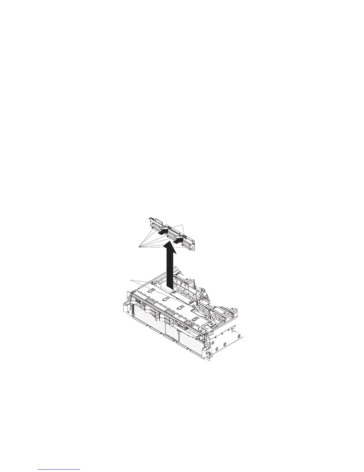
SAS backplane
To remove the Serial Attached SCSI (SAS) backplane, complete the following steps.
Release tabs
Guide channels
SAS connectors
1. Read the safety information that begins on page vii, and “Handling
static-sensitive devices” on page 100.
2. Turn off the server and peripheral devices, and disconnect the power cords and
all external cables necessary to replace the device.
3. Remove the top cover.
4. Pull the hard disk drives out of the server slightly to disengage them from the
SAS backplane.
122 IBM xSeries 366 Type 8863: Problem Determination and Service Guide
 Loading...