Many errors are first indicated by a lit information LED or system-error LED on the
operator information panel on the front of the server. If one or both of these LEDs
are lit, one or more LEDs elsewhere in the server might also be lit and can direct
you to the source of the error.
Note: Read the safety information beginning on page vii and “Handling
static-sensitive devices” on page 100.
View the LEDs in the following order:
1. Check the operator information panel on the front of the server.
v If the information LED is lit, it indicates that information about a suboptimal
condition in the server is available in the BMC log or in the system-error log.
Important: If the server has a baseboard management controller, clear the
BMC log and system-event log after you resolve all conditions. This will turn
off the information LED and LOG LED, if all conditions are resolved.
v If the system-error LED is lit, it indicates that an error has occurred; go to
step 2.
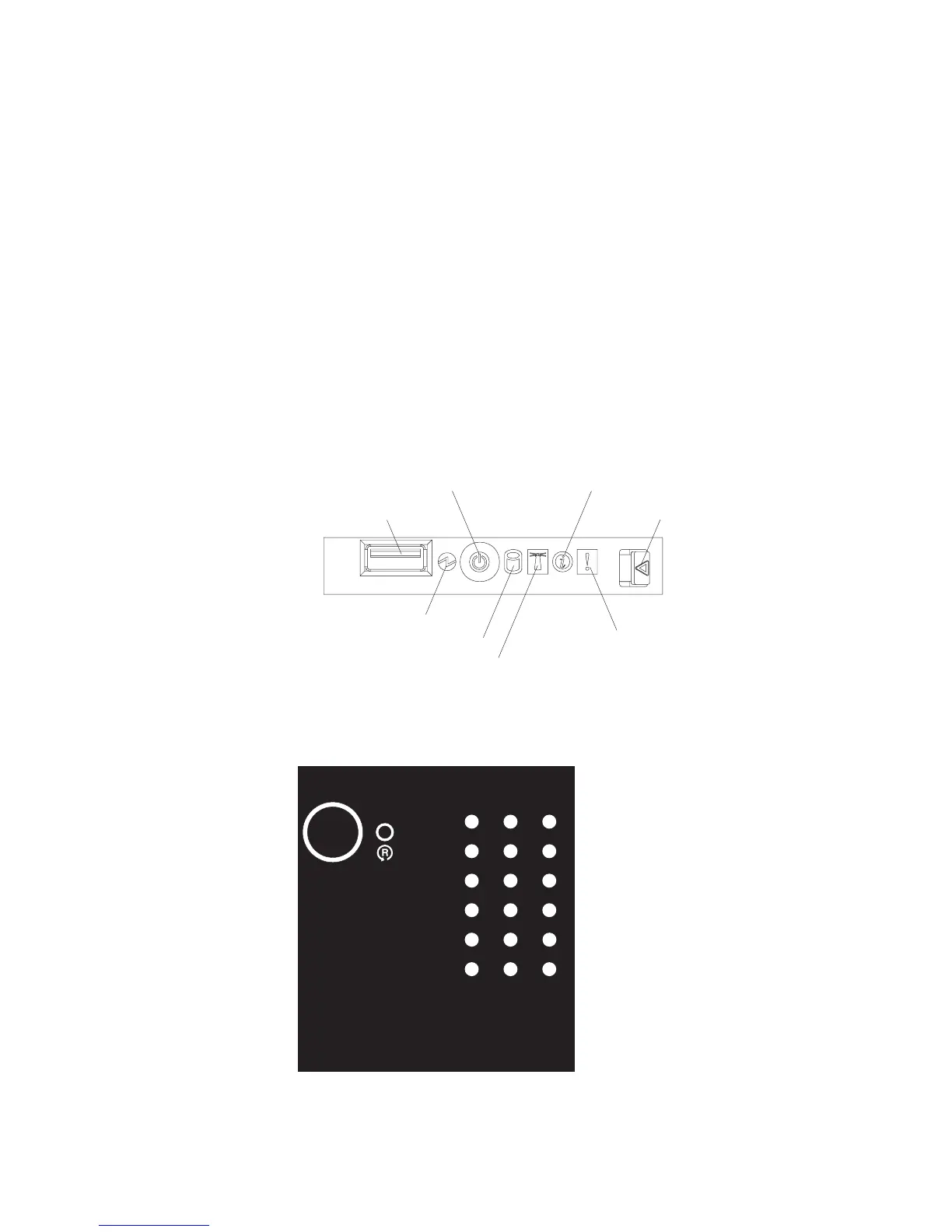
The following illustration shows the operator information panel.
Power-control button
Power-on LED
USB connector
Hard disk drive activity LED
Information LED
System-error LED
Locator LED
Release latch
2. To view the light path diagnostics panel, press the release latch on the front of
the operator information panel to the left; then, slide it forward. This reveals the
light path diagnostics panel. Lit LEDs on this panel indicate the type of error that
has occurred.
DASD
NMI
PCI
BRD
I/O
BRD
PS
NONRED
SP
LINK
RAID
MEM
CPU
CPU
BRD
FAN
PCI
VRM
OVER SPEC
TEMP
REMIND
LOG
Light Path
Diagnostics
Look at the system service label on the top of the server, which gives an
overview of internal components that correspond to the LEDs on the light path
Chapter 2. Diagnostics 49
 Loading...