EasyManua.ls Logo

IBM FlashSystem 5000 Series User Manual

IBM FlashSystem 5000 Series
106 pages
To Next Page IconTo Next Page
To Previous Page IconTo Previous Page
Page #74 background image
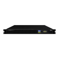
Figure 53. Secure power cables
Important: Always secure each power cable with a cable retainer and ensure that the cable is
installed along one of the cable management arms. When secured, the power and SAS cables stay
connected when you slide the expansion enclosure out of the rack to perform service tasks.
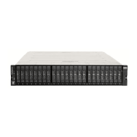
Figure 54. Power and SAS cable connections on the back of the enclosure
3. Verify that the expansion enclosure and its components are operating as expected.
On the back of the expansion enclosure, all four fans and the expansion canister indicators ( 3 and 8
in Figure 55 on page 56) become active when the power is connected.
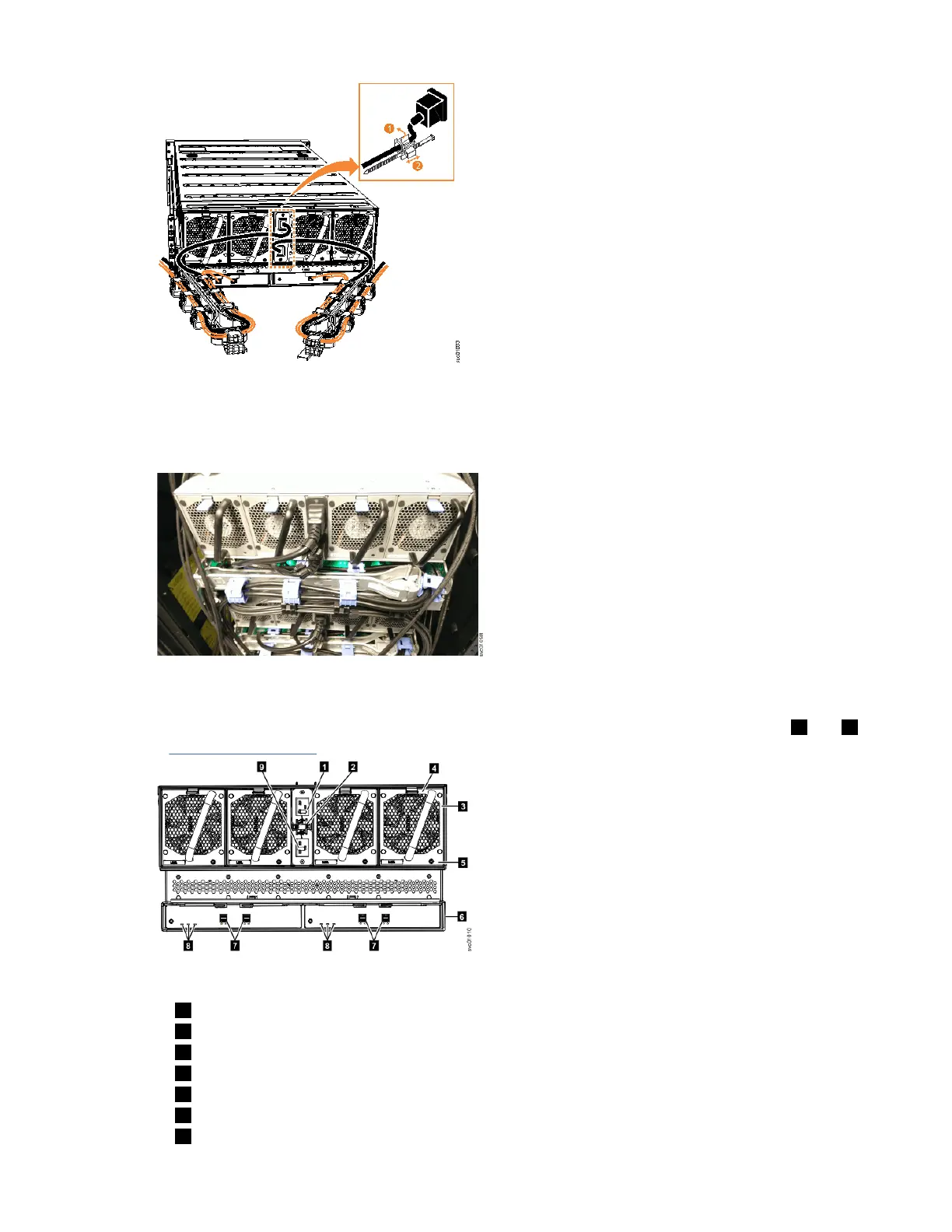
Figure 55. Features on the rear of the 5U expansion enclosure
1 Power cable connector for PSU 2
2 Power cable retention clamps
3 Fan module
4 Fan release latch
5 Fan fault indicator
6 Expansion canister
7 SAS ports and indicators
56
IBM FlashSystem 5000 : FlashSystem 5000 Quick Installation Guide

Table of Contents

Question and Answer IconNeed help?

Do you have a question about the IBM FlashSystem 5000 Series and is the answer not in the manual?

IBM FlashSystem 5000 Series Specifications

General IconGeneral
ModelIBM FlashSystem 5000 Series
Storage TypeFlash
Management SoftwareIBM Spectrum Virtualize
Form Factor2U
Drive TypesSAS
RAID SupportRAID 5, RAID 6
Host Interface16 Gbps Fibre Channel, 25 Gbps iSCSI, 12 Gbps SAS
Data ReductionYes (compression, deduplication)
EncryptionYes
ReplicationYes, Metro Mirror, Global Mirror
Operating System SupportWindows, Linux, AIX, IBM i
Cache64GB

Summary

Safety and environmental notices

Caution notices for the system

Understanding and adhering to caution notices specific to the IBM FlashSystem 5000.

Before you begin the installation

Identify the hardware components

Familiarizing with hardware components and port locations before system installation.

Installing the system hardware

Installing support rails for the system

Procedure for installing support rails for control and expansion enclosures in a rack.

Installing enclosures

Steps for physically installing control and expansion enclosures into a rack.

Configuring the system

Initialize system by using the technician port

Step-by-step guide to initialize the system using a technician port connection.

Related product manuals