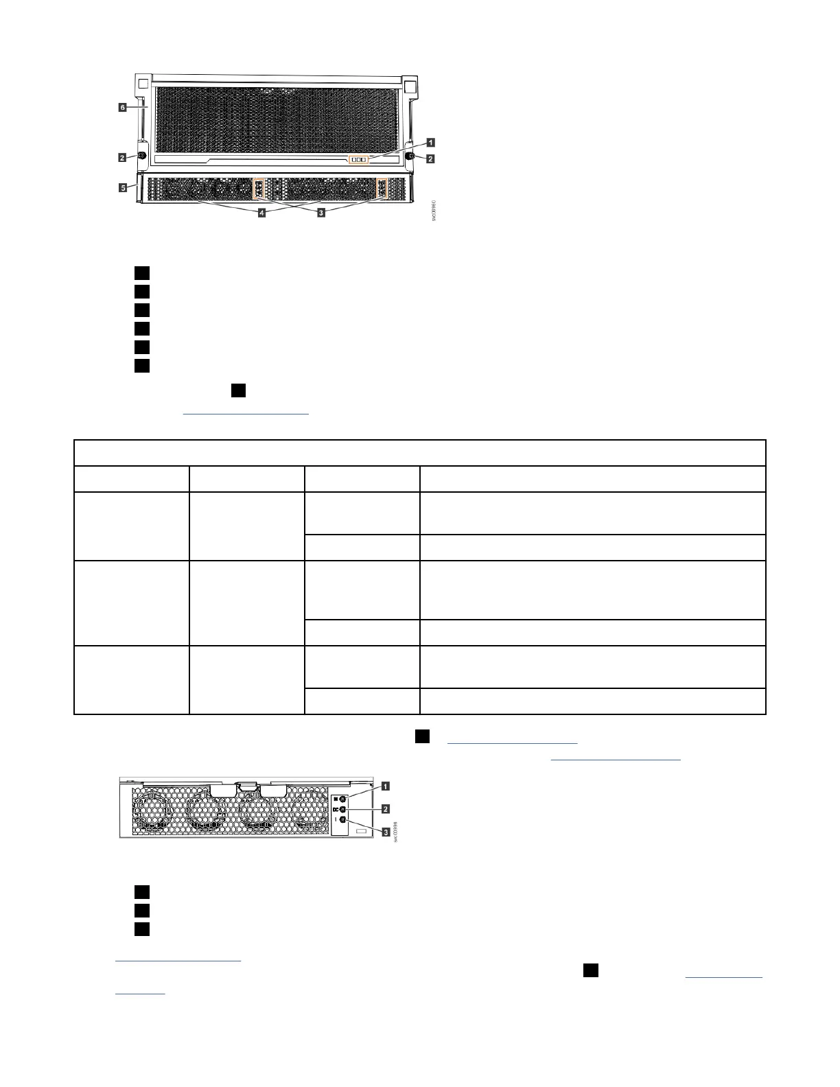
Figure 56. LEDs on the front of the expansion enclosure
1 Display panel LEDs
2 Rack retention thumb screws
3 Power supply unit LEDs
4 Power supply units (PSUs)
5 PSU fascia (1U)
6 Front fascia (4U)
The display panel ( 1 ) contains three LEDs that describe the operational status of the expansion
enclosure. Table 29 on page 58 describes the function and meaning of the LEDs on the front display
panel.
Table 29. Display panel LEDs
Function Color Status Description
Power Green On The expansion enclosure power is on; this LED is
controlled by the expansion enclosure.
Off The expansion enclosure power is off.
Identify Blue On Identies the expansion enclosure; this LED is
controlled by the system. Use the management GUI or
service interface to identify an enclosure.
Off The expansion enclosure is operating normally.
Enclosure fault Amber On The expansion enclosure is coming up or a fault is
detected against a component within the enclosure.
Off No faults are detected.
The 5U expansion enclosure contains two PSUs ( 4 in Figure 56 on page 58) that are accessible from the
front of the enclosure. Each PSU has its own a set of LEDs, as shown in Figure 57 on page 58.
Figure 57. LEDs on the front of a power supply unit
1 Input power
2 DC power
3 Fault indicator
Table 30 on page 59 explains the function and status that is indicated by each of the LEDs. The power
cords for each PSU are accessible from the rear of the expansion enclosure ( 1 ), as shown in Figure 60 on
page 60.
58
IBM FlashSystem 5000 : FlashSystem 5000 Quick Installation Guide