Chapter 2: Hardware Installation 27
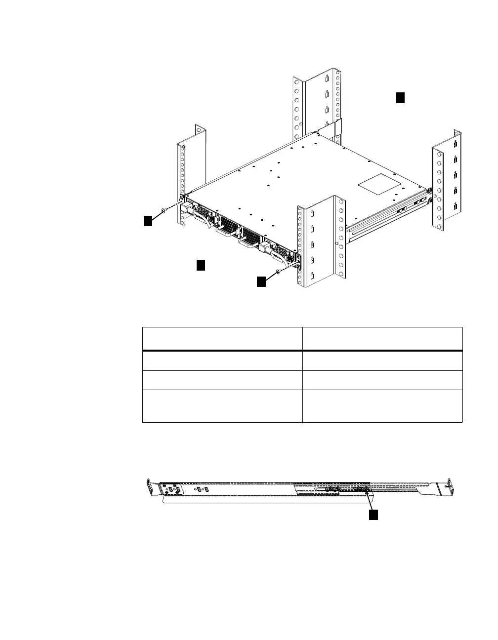
The table below lists the descriptions for each label in the diagram.
Ensure that the switch is well-seated. Use two 10-32 screws (one for each
side) to fix the rear end of the switch to the tie-down feature on the rail. The
diagram below is of a left rail.
Label Description
1 The rear portion of the rack
2 The front portion of the rack
3 The M5 screws used to fix the front
side of the switch to the rails.

 Loading...


