EasyManuals Logo

IBM Storwize V5000 Gen2 User Manual

IBM Storwize V5000 Gen2
204 pages
To Next Page IconTo Next Page
To Previous Page IconTo Previous Page
Page #111 background imageLoading...
Page #111 background image
Remove the bottom (1U) fascia
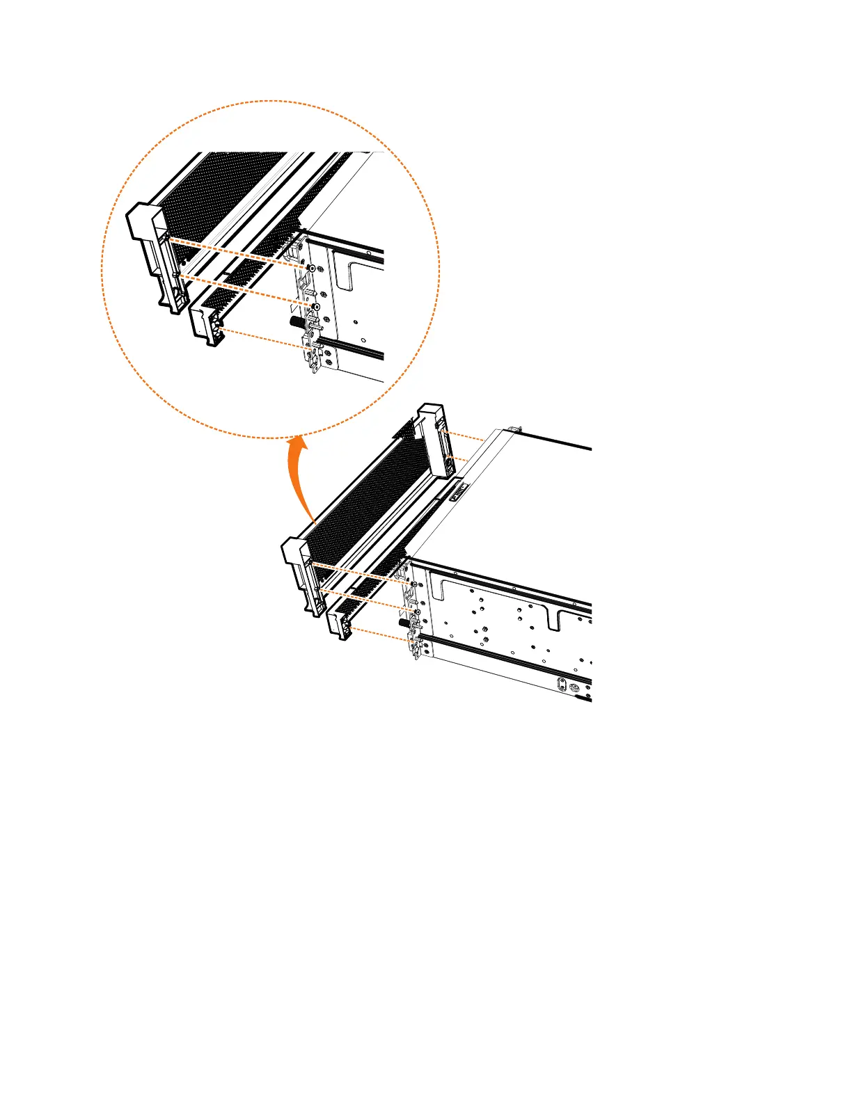
3. Gently pull on each side of the PSU fascia to remove it from the chassis, as
shown in Figure 74. The PSU fascia disengages from the slot and pin that
connect it to each side of the chassis.
You must remove the bottom fascia to access and service either PSU. However,
as Figure 75 on page 88 shows, you do not have to remove the front fascia.
svc01043
Figure 74. Remove fascia components from the expansion enclosure
Chapter 2. Installing the system hardware 87

Table of Contents

Questions and Answers:

Question and Answer IconNeed help?

Do you have a question about the IBM Storwize V5000 Gen2 and is the answer not in the manual?

IBM Storwize V5000 Gen2 Specifications

General IconGeneral
ModelStorwize V5000 Gen2
Storage TypeHybrid Flash Array
Form Factor2U
Maximum Drives240
Operating SystemIBM Spectrum Virtualize
Drive TypesSSD
RAID Levels0, 1, 5, 6, 10
Host Interface8 Gbps Fibre Channel (FC), 16 Gbps Fibre Channel (FC), 10 Gbps iSCSI, 12 Gbps SAS
Drive Bays24
Cache MemoryUp to 64 GB
Power SupplyRedundant, hot-swappable power supplies
VirtualizationYes

Related product manuals