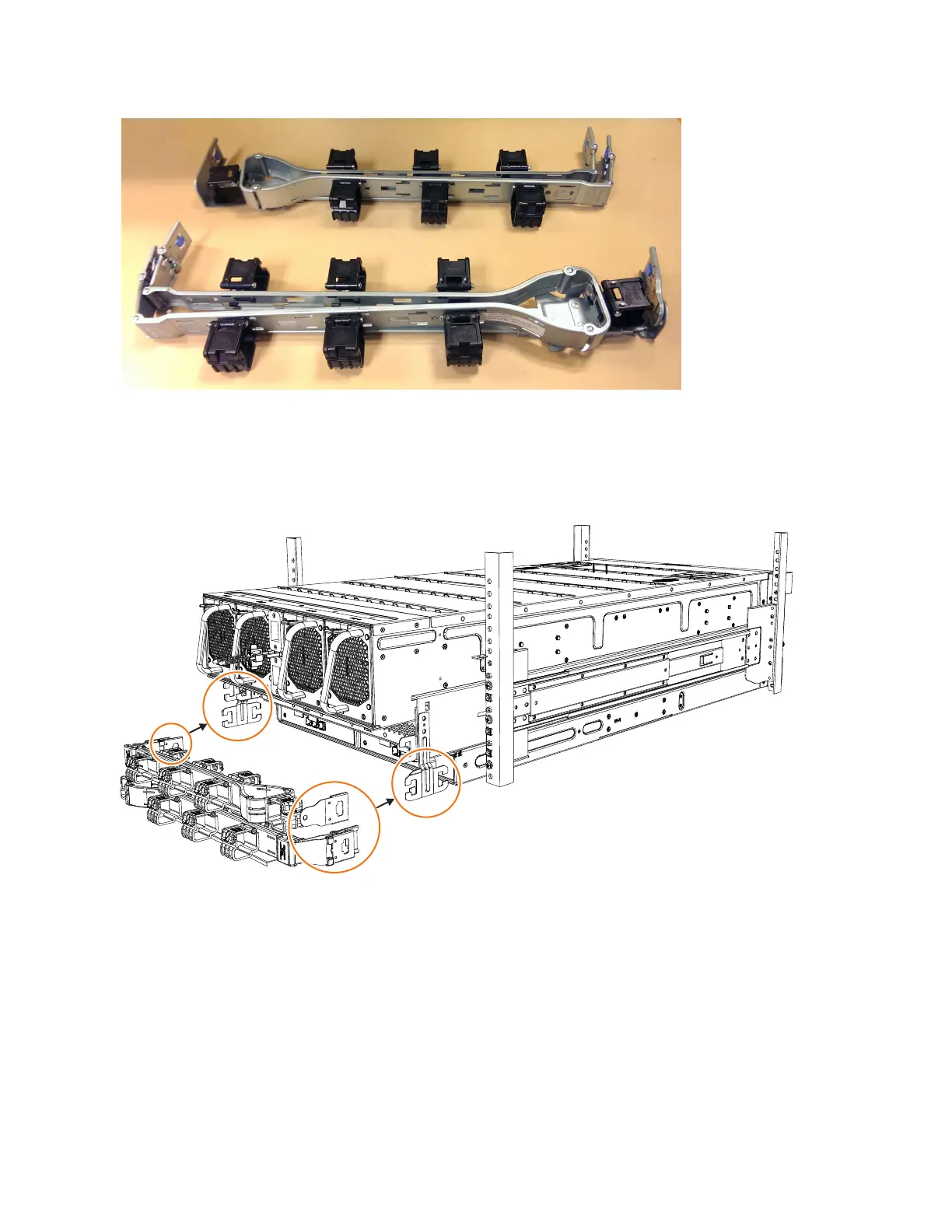
As Figure 50 shows, the support rail connectors of each CMA assembly are
installed on the rail hooks at the end of the support rails.
Procedure
1. Remove the loop straps from the upper and lower CMA assemblies. The straps
are used only for shipping.
Installing the upper CMA assembly
Figure 51 on page 68 shows the connectors on the upper CMA assembly.
Figure 49. Upper and lower cable-management arms
Figure 50. Upper and lower cable-management arms
Chapter 2. Installing the system hardware 67

 Loading...


