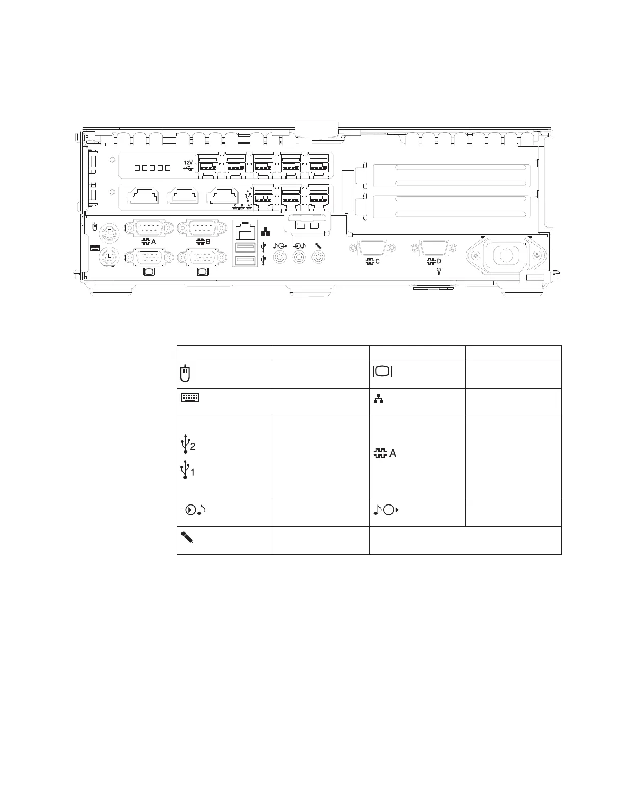
Figure 7 shows a view of the rear-panel I/O connections. The top adapter card is
chosen based on the application, while the bottom adapter card is available on all
models. Table 6 defines the icons that label each connection.
Table 6. Connection icons definitions
Icon Definition Icon Definition
PS/2 mouse Display 1 and 2
PS/2 keyboard Ethernet LAN
USB 2.0
External serial
devices (such as a
scale and a scanner)
A and B (and C and
D Models 743, C43,
E43, 783, E83, 784,
C84, and E84)
Line (audio) in Line (audio) out
Microphone
9A9A
2
1
100-127V, 4A Max.100-127V, 4A Max.
200-240V, 2A Max.200-240V, 2A Max.
11 22
H G EF D
CD BCD B CD ACD A
1
2
Figure 7. Rear panel
Chapter 1. Introducing the SurePOS 700 models 13
 Loading...