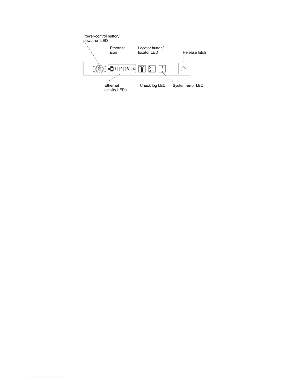
v Power-control button and power-on LED: Press this button to turn the server
on and off manually. The states of the power-on LED are as follows:
Off: Power is not present or the power supply, or the LED itself has failed.
Flashing rapidly (4 times per second): The server is turned off and is not
ready to be turned on. The power-control button is disabled. This will last
approximately 5 to 10 seconds.
Flashing slowly (once per second): The server is turned off and is ready to
be turned on. You can press the power-control button to turn on the server.
Lit: The server is turned on.
v Ethernet activity LEDs: When any of these LEDs is lit, they indicate that the
server is transmitting to or receiving signals from the Ethernet LAN that is
connected to the Ethernet port that corresponds to that LED.
v System-locator button/LED: Use this blue LED to visually locate the server
among other servers. A system-locator LED is also on the rear of the server. This
LED is used as a presence detection button as well. You can use IBM Systems
Director or IMM2 web interface to light this LED remotely. This LED is controlled
by the IMM2. The locator button is pressed to visually locate the server among
the others servers.
v Check log LED: When this yellow LED is lit, it indicates that a system error has
occurred. Check the error log for additional information. See the Problem
Determination and Service Guide on the System x Documentation CD for more
information about error logs.
v System-error LED: When this yellow LED is lit, it indicates that a system error
has occurred. A system-error LED is also on the rear of the server. An LED on
the light path diagnostics panel on the operator information panel or on the
system board is also lit to help isolate the error. This LED is controlled by the
IMM2.
Light path diagnostics panel
The light path diagnostics panel is located on the top of the operator information
panel. For additional information about the LEDs on the light path diagnostics panel,
see “Light path diagnostics LEDs” on page 17.
Note: The system service label inside the server cover also provides information
about the location of the light path diagnostics LEDs.
To access the light path diagnostics panel, press the blue release latch on the
operator information panel. Pull forward on the panel until the hinge of the operator
information panel is free of the server chassis. Then pull down on the panel, so that
you can view the light path diagnostics panel information.
Chapter 1. The System x3550 M4 server 15

 Loading...


