Notes:
1. You can install DIMMs for microprocessor 2 as soon as you install
microprocessor 2; you do not have to wait until all of the DIMM slots for
microprocessor 1 are filled.
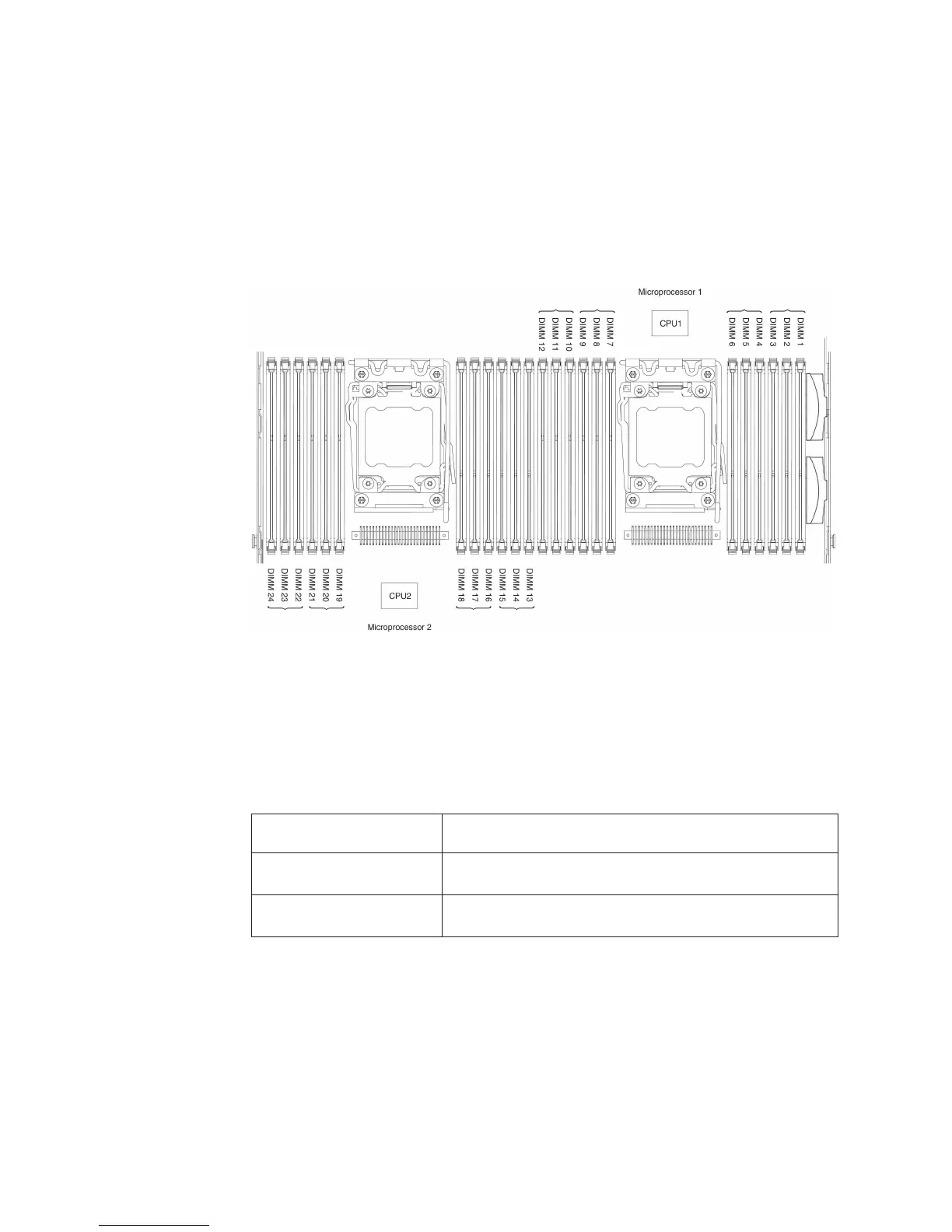
2. DIMM slots 13-24 are reserved for microprocessor 2; thus, DIMM slots 13-24
are enabled when microprocessor 2 is installed.
The following illustration shows the location of the DIMM connectors on the system
board.
DIMM installation sequence
Depending on the server model, the server may come with a minimum of one 2 GB
or 4 GB DIMM installed in slot 1. When you install additional DIMMs, install them in
the order shown in the following table to optimize system performance. In general,
all three channels on the memory interface for each microprocessor can be
populated in any order and have no matching requirements.
Table 7. Normal mode DIMM installation sequence
Number of installed
microprocessor DIMM connector population sequence
One microprocessor
installed
1, 4, 9, 12, 2, 5, 8, 11, 3, 6, 7, 10
Two microprocessors
installed
1, 13, 4, 16, 9, 21, 12, 24, 2, 14, 5, 17, 8, 20, 11, 23, 3, 15,
6, 18, 7, 19, 10, 22
Memory mirrored channel
Memory mirrored channel mode replicates and stores data on two pairs of DIMMs
within two channels simultaneously. If a failure occurs, the memory controller
switches from the primary pair of memory DIMMs to the backup pair of DIMMs. You
can enable memory mirrored channel in the Setup utility (see “Starting the Setup
utility” on page 109). When you use the memory mirrored channel feature, consider
the following information:
62 IBM System x3550 M4 Type 7914: Installation and User’s Guide

 Loading...


