1 and DIMM connector 4. However, the size, speed, type, and technology of
the DIMMs that you install in DIMM connector 7 and DIMM connector 10 must
match each other.
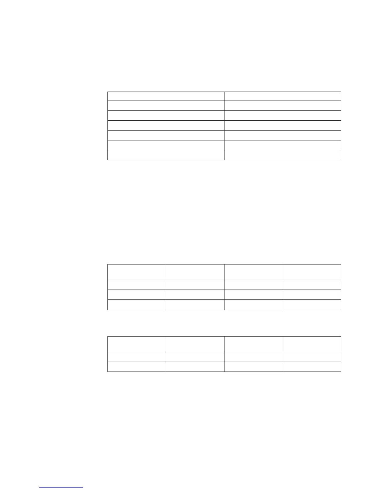
– The following table shows the DIMM upgrade configuration sequence for
operating in non-mirroring mode (normal mode).
Table 4. 5. DIMM upgrade configuration sequence in non-mirroring mode
Number of DIMMs DIMM connectors
2 1, 4
4 1, 4, 7, 10
6 1, 4, 7, 10, 2, 5
8 1, 4, 7, 10, 2, 5, 8, 11
10 1, 4, 7, 10, 2, 5, 8, 11, 3, 6
12 1, 4, 7, 10, 2, 5, 8, 11, 3, 6, 9, 12
v The amount of usable memory is reduced depending on the system
configuration. A certain amount of memory must be reserved for system
resources. To view the total amount of installed memory and the amount of
configured memory, run the Configuration/Setup Utility program and select
System Summary from the menu. For additional information, see Chapter 3,
“Configuring the server,” on page 49.
v The following tables show examples of maximum memory capacity when the
server operates in mirroring and non-mirroring modes, using identical single-rank,
x8 technology or double-rank, x4 technology DIMMs. The memory capacity is
dependent on the size and technology of the DIMMs that you install.
Table 5. Example of the memory capacity when identical x8 technology single-rank DIMMs
are used
DIMMs installed
x8 single-rank
technology
Memory available in
mirroring mode
Memory available in
non-mirroring mode
8 512 MB 2 GB 4 GB
8 1 GB 4 GB 8 GB
8 2 GB 8 GB 16 GB
Table 6. Example of the memory capacity when identical x4 technology double-rank DIMMs
are used
DIMMs installed
x4 double-rank
technology
Memory available in
mirroring mode
Memory available in
non-mirroring mode
8 512 MB 8 GB 16 GB
8 1 GB 16 GB 32 GB
v When you restart the server after you add or remove a DIMM, the server
displays a message that the memory configuration has changed.
v If a problem with a DIMM is detected, light path diagnostics lights the
system-error LED on the front of the server, indicating that there is a problem,
and guides you to the defective DIMM. When this occurs, first identify the
defective DIMM; then, remove and replace the DIMM.
Chapter 2. Installing optional devices 37
 Loading...