24
Instruction Manual IMBus
- In addition to the IMB-sm1/2/4 modules connection cables / -adapters for the connection of the par-
ticular gauges are offered.
2. Configuration :
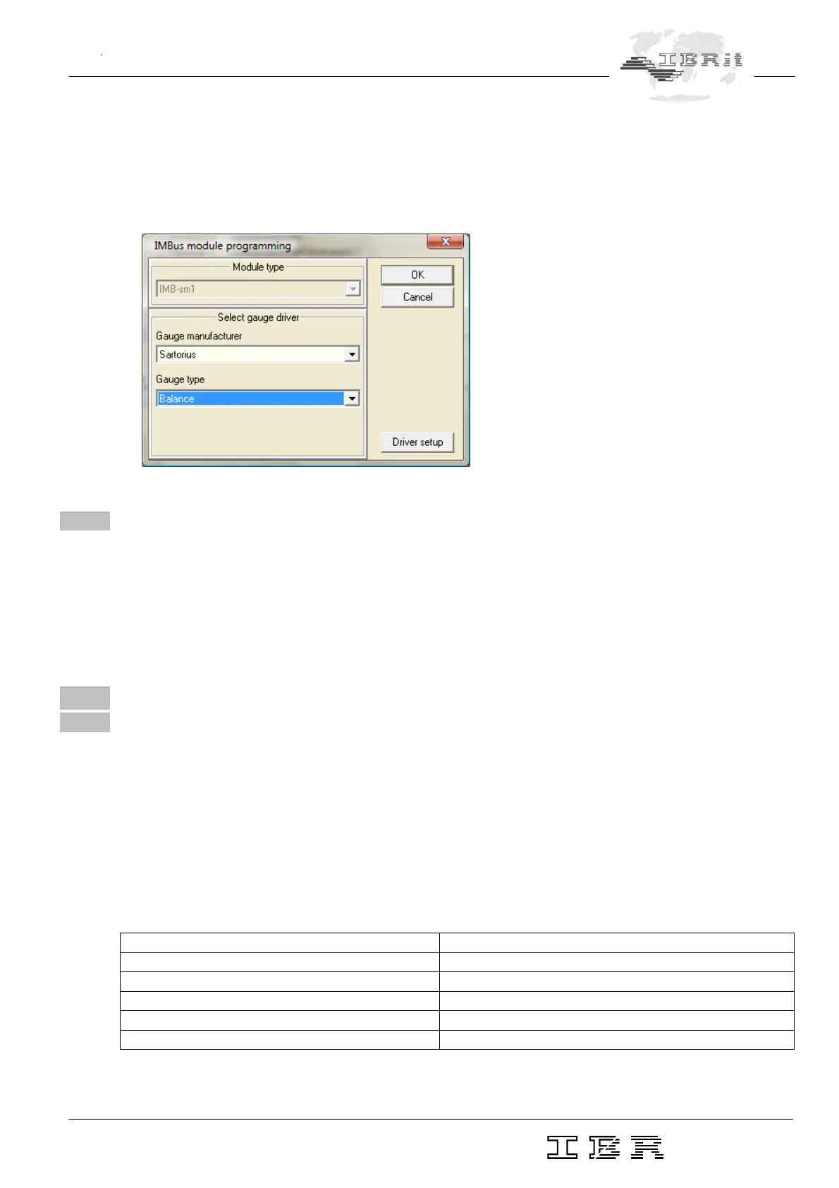
- Open Setup-Window of IMB_Test programme.
- Press Setup-Button behind the input ( Column Gauge / Sensor ) :
- Selection of the gauge
5.8 IMB-pm1
1. Short description :
- The IMB-pm1 modules allow the connection of gauges with „old“ parallel interface.
2. Configuration :
- see 5.7.2.
6 Wiring of IMBus switching modules
6.1 IMB-io4
1. Short description :
- The IMBus input and output modules are all galvanically ( 2kV ) separated.
- The inputs are compatible to PLC optocoupler inputs and work in a wide voltage area.
- The outputs are ESD proofed, short circuit proofed and contain a high driver power.
- Each in-/output contains a state LED.
- The connections are done by plugable terminal strips.
2. Technical data :
Electrical characteristics “Input”
Nominal input voltage 24 V DC
Input voltage signal “High” 13 V … 30 V
Input voltage signal “Low” -30 V ... + 5 V
Input current signal “High” typ. 7 mA
Connection of 2-wire-BEROS is possible max. current 1,5 mA
Isolation voltage 2000 V