7
Instruction Manual IMBus
1.) Replace the screws at the IMBus modules by the pins included in the shipment of the IMB-Extension
cables.
2.) Plug IMB-Extension cable in and screw it fix.
2.7 Connection of hand / foot switches
The IMBus allows the management of several hand / foot switches. To each IMBus module a separate
hand / foot switch can be connected.
Example :
Addr.7 Addr.6 Addr.5 Addr.4 Addr.3 Addr.2 Addr.1
The hand switch affects the module with Addr.1 & Addr.2.
The foot switch affects the two modules with Addr.3 to Addr.7.
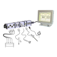
2.8 Connection of gauges and sensors
1.) Plug gauge / sensor cable in.
2.) The addresses are automatically assigned in following order ( starting at the PC connection ) :
Addr.7 Addr.6 Addr.5 Addr.4 Addr.3 Addr.2 Addr.1