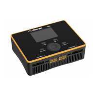
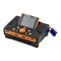
DX8
Dual Balance Charger/Discharger/DC Power
Buttons Function & Icons Description
Please refer to below chart for button functions
Initial interface: Enter CHANNEL SELECTION
Other interface: Confirm function or enter submenu
Press the round button
for 2 seconds
Startup interface: Enter SELECT INPUT POWER SUPPLY
Initial interface: Enter SYSTEM MENU
MEMORY SELECTION interface: Enter Program Management
Menu
Other interface: Save and return to Previous Menu
Turn anticlockwise: The menu scrolls up or the adjustment
value becomes smaller
Turn clockwise: The menu scrolls down or the adjustment
value becomes larger
When the round button is pressed and turned the rotary switch
one time at the same time, it will be triggered automatically and
continuously before releasing the pressed button.
Program runtime: Switch the display information page of
CH-x channel
Press STATUS-x for 2
seconds
Initial interface: Start internal resistance measurement
Program runtime: The parameter change interface pops up
Initial interface: Enter MEMORY SELECTION; click again to
return the initial interface
Program runtime: Stop running program
Press STOP/START-x for 2
seconds
Initial interface: Enter Run Program
Run Program Interface: Run the selected program
< STATUS-x> +
< STOP/START-x>
Press STATUS-x and
STOP/START-x at the same
time for 2 seconds
Initial Interface: Enter MONITOR SETTINGS
Press STOP/START-1 and
STOP/START-2 at the same
time for 2 seconds
Run Program interface: CH-1 and CH-2 run the same program
.Familiarity with the icons on the interface will help you better understand the working status of the charger, as shown in
following chart:
Fan status: a. Grey shows not running
b. Green shows running (the higher the green shows, the faster the fan runs, and vice versa)
SD card status: a. Grey shows the SD card is not inserted
b. Green shows the SD card has been inserted and can be used normally
USB status: a. Grey for no USB connection
b. Green for USB connection
c. Data transfer to PC, red dot flashes
TYPE-C PD charge permit function