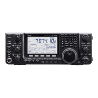
To raise the stand:
With the transceiver upside down, pull the stand
towards the rear panel and then upwards, as illus-
trated below.
10
2
INSTALLATION AND CONNECTIONS
■ Installation
D Single body mounting D Stand
D Front panel separation
D Front panel mounting
➀ While pulling the panel release button towards you,
slide the front panel to the right (fig. 1).
➁ Attach the optional OPC-581 to the main body and
tighten the supplied screw as in fig. 2.
➂ Attach the other end of the OPC-581 to the
detached front panel as in fig. 3.
➀ Attach the MB-63 to a flat surface using the two
supplied screws (fig. 1).
➁ Fix the detached front panel to the MB-63 as illus-
trated in fig. 2.
Be careful of the orientation of the MB-63, other-
wise, the front panel may become attached in the
opposite direction.
 Loading...