• ACC SOCKET
• When connecting the ACC conversion cable (OPC-599)
6
1
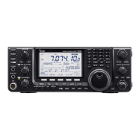
PANEL DESCRIPTION
!3 BEEP/SIDETONE CONTROL [BEEP/SIDETONE]
Adjusts the beep tone and CW side tone audio lev-
els.
TECHNICAL INFORMATION
ACC PIN # NAME DESCRIPTION SPECIFICATIONS COLOR
1 8 V Regulated 8 V output.
Output voltage : 8 V ±0.3 V
Output current : Less than 10 mA
brown
2 GND Connects to ground. red
3 HSEND
Input/output pin (HF/50 MHz).
Goes to ground when transmitting.
When grounded, transmits (connected to 8V
line thru 2.2 kΩ resistance/144 MHz operation)
.
Ground level : –0.5 V to 0.8 V
Input current : Less than 20 mA
(HF/50 MHz bands)
orange
4 BDT Data line for the optional AT-180. yellow
5 BAND
Band voltage output.
(Varies with amateur band)
Output voltage : 0 to 8.0 V green
6 ALC ALC voltage input.
Control voltage : –4 to 0 V
Input impedance : More than 10 kΩ
blue
7 VSEND
Input/output pin (144 MHz).
Goes to ground when transmitting.
When grounded, transmits
(connected to 8V
line thru 2.2 kΩ resistance/HF•50 MHz operation)
.
Ground level : –0.5 V to 0.8 V
Input current : Less than 20 mA
(144 MHz band)
purple
8 13.8 V 13.8 V output when power is ON. Output current : Max. 1 A gray
9 TKEY Key line for the AT-180. white
10 FSKK
RTTY keying input.
Connected in parallel to the [RTTY] jack.
Ground level : –0.5 to 0.8 V
Input current : Less than 10 mA
black
11 MOD Modulator input.
Input impedance : 10 kΩ
Input level : Approx. 100 mV
rms
pink
12 AF
AF detector output.
Fixed, regardless of [AF] position.
Output impedance : 4.7 kΩ
Output level : 100 to 350 mV rms
light
blue
13 SQLS
Squelch output.
Goes to ground when squelch opens.
SQL open : Less than 0.3 V/5 mA
SQL closed : More than 6.0 V/100 µA
light
green
 Loading...