©POWER
SWITCH
ON
OFF
This
is
a push-lock
switch which controls
the input
DC power
to
the
IC-751A.
When
the IC-PS30
AC
power
supply is
used, the
switch also
acts as the
AC
power supply switch.
Power is
supplied to
the transceiver
when the switch
is pushed IN and
locked.
Power
to
all
circuits
is
cut (except
to the
PA
unit when
using
a
DC power
supply) when
the switch is pushed
again and
released.
©AUTOMATIC
GAIN
CONTROL
SWITCH
[AGC]
AGC
©METER
SWITCH
METER
COMP
©TRANSMIT/RECEIVE
(T/R)
SWITCH
TRANSMIT
RECEIVE
This switch changes
the time
constant of
the AGC
circuit.
In
the
SLOW position, the
AGC
voltage releases slowly for SSB reception.
In the FAST position, the
AGC voltage releases
quickly
suitable for
receiving
CW
signals or signals
with rapid
fading.
In
the
OFF
position,
the AGC circuit and S-meter
are disabled.
Also, the
AGC circuit does not actuate in
the
FM
mode.
In the
transmit mode, the front panel meter has six functions.
Vc Indicates the
collector voltage of the
final
transistors.
Ic
Indicates the collector current of the
final transistors.
COMP
Indicates
the compression
level
when the
speech
compressor Is
in use.
ALC
Indicates the
ALC
level. The
ALC circuit begins
to
function
when the RF
output power
reaches
a
preset
level.
Po
Indicates
the approximate output power.
SWR
Indicates
the
SWR
of the
antenna system after
the
meter
is
referenced at "SET"
while
the
Po
meter
function
is selected.
This
switch
is
for
manually changing between transmit and receive.
Set the switch
to RECEIVE (down)
to
place
the IC-751A
in
the
receive
mode. Move the
switch
to
TRANSMIT (up) to change to
the transmit
mode. When using
the
PTT
SWITCH on the micro-
phone or VOX
operation, the T/R
SWITCH
must be
at
RECEIVE.
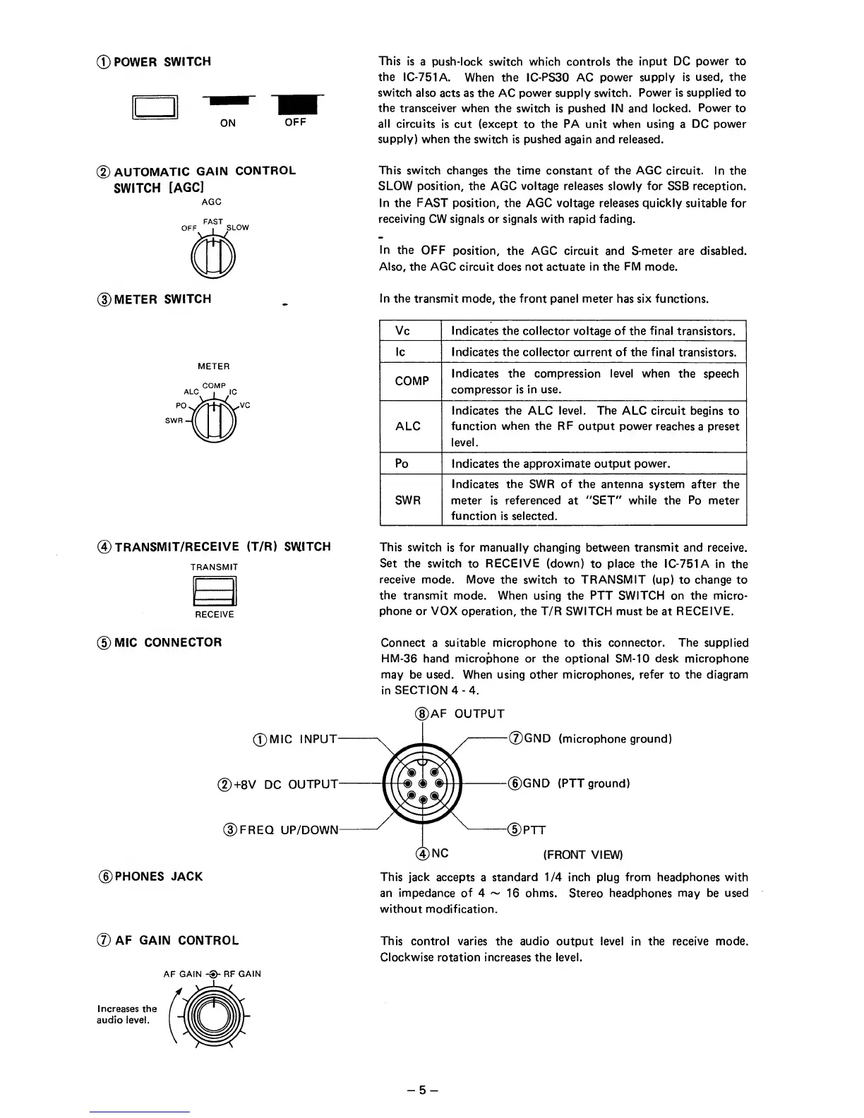
)MIC
CONNECTOR
©MIC
INPUT
@+8V DC
OUTPUT
©FREQ
UP/DOWN
©PHONES JACK
Connect
a
suitable microphone
to
this connector. The supplied
HM-36 hand microphone or the optional SM-10 desk microphone
may be used.
When
using other microphones, refer
to
the diagram
in
SECTION
4
-4.
©AF OUTPUT
©GND
(microphone ground)
©GND
(PTT
ground)
-(Dptt
(FRONT VIEW)
This jack accepts
a
standard
1/4
inch
plug
from
headphones with
an impedance of
4
~
16
ohms.
Stereo headphones may
be used
without modification.
@
AF GAIN
CONTROL
AF
GAIN RF
GAIN
Increases the
audio level.
This
control varies the audio
output
level
in
the receive mode.
Clockwise
rotation increases the level.
-
5
-