6
CONNECTIONS AND INSTALLATION
15
u TUNER RECEPTACLE
Connects a control cable to an optional AT-130
AN
-
TENNA TUNER
. A female connector is supplied for
connection.
i DC POWER RECEPTACLE
Connects to a regulated 12–16 V DC power source
such as a 12 V battery or DC power supply using
the supplied DC power cable.
R CAUTION: DO NOT connect to a 24 V battery.
This will damage the transceiver.
o FUSE HOLDERS
Hold two 30 A fuses for +ve and –ve terminals. Re-
place both fuses when one fuse is blown.
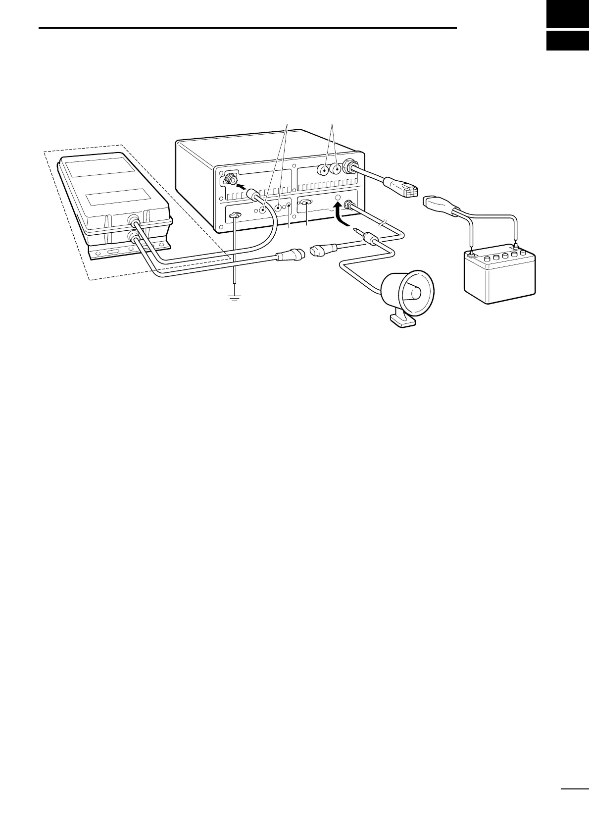
■ Connections on rear panel
q ANTENNA CONNECTOR (p. 19)
Connects a 50 Ω HF band antenna with a 50 Ω
matched coaxial cable and a PL-259 plug.
w GROUND TERMINAL
IMPORTANT! Connects a ship’s (or vehicle’s)
ground. See p. 18 for details.
e ACC(1) and ACC(2) SOCKETS
See p. 16 for details.
r CLONE JACK
For Dealer use only.
t REMOTE SOCKET (p. 17)
REMOTE socket for Marine and General versions.
y EXTERNAL SPEAKER JACK
Connects a 4–16 Ω external speaker using a
1
⁄4"
monaural plug. This external audio is not muted by
the [SPEAKER] switch on the front panel.
■ Unpacking
Microphone (EM-101) . . . . . . . . . . . . . . . . . . . . . . 1
Microphone hanger . . . . . . . . . . . . . . . . . . . . . . . . 1
DC power cable (OPC-568) . . . . . . . . . . . . . . . . . 1
Mounting bracket . . . . . . . . . . . . . . . . . . . . . . . . . . 1
Bracket knobs (8820000170) . . . . . . . . . . . . . . . . 4
CONNECTORS
DIN connector (8-pin for ACC1) . . . . . . . . . . . . . . 1
DIN connector (7-pin for ACC2) . . . . . . . . . . . . . . 1
Speaker plug (5610000040) . . . . . . . . . . . . . . . . . 1
Tuner connector (56100000150) . . . . . . . . . . . . . . 1
Pins for tuner connector (6510019030) . . . . . . . . . 4
NUTS AND BOLTS
Allen bolt (M6 × 50) . . . . . . . . . . . . . . . . . . . . . . . . 4
Self-tapping screws (M6 × 30) . . . . . . . . . . . . . . . . 4
Nuts (M6; use 2 pcs. for each bolt) . . . . . . . . . . . . 8
Flat washers (M6) . . . . . . . . . . . . . . . . . . . . . . . . . 8
Spring washers (M6) . . . . . . . . . . . . . . . . . . . . . . . 4
Self-tapping screws
(3.5 × 30 for mic. hanger) . . . . . . . . . . . . . . . . 2
FUSES
FGB 30 A (rear panel) . . . . . . . . . . . . . . . . . . . . . . 2
FGB 5 A (internal) . . . . . . . . . . . . . . . . . . . . . . . . . 2