2
2
PANEL DESCRIPTION
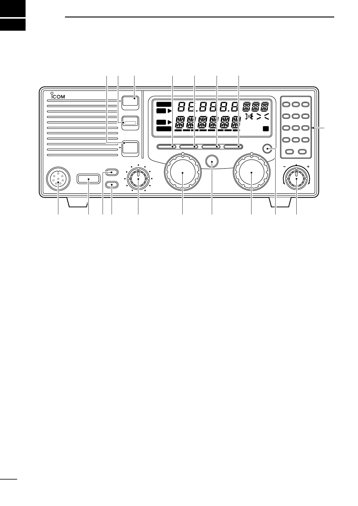
■ Front panel
q MICROPHONE CONNECTOR (p. 16)
Accepts the supplied microphone or an optional
handset.
☞ NOTE: No audio is output via the speaker when the
microphone or handset is not connected.
w POWER SWITCH [POWER]
Turns power on and off.
e SPEAKER SWITCH [SPEAKER]
Turns the built-in speaker on and off.
•“è” appears in the display while the speaker is turned
off.
• Any external speaker connected to the rear panel is not
turned off.
r DISPLAY INTENSITY SWITCH [DIMMER]
Turns the display backlighting on and off.
t VOLUME CONTROL [VOLUME]
Adjusts the audio output level.
• Audio does not come from the speaker when:
➟ A microphone is not connected.
➟ The [SQL] switch is turned on and no signal is being
received.
y GROUP CHANNEL SELECTOR [GROUP]
➥ In memory mode, selects 1 of 3 channel groups
(“A,” “B” or “C”). (p. 5)
• In VFO mode, no function.
➥ Selects an item in set mode. (p. 11)
u ANTENNA TUNE SWITCH [TUNE] (p. 8)
Tunes the connected tuner to the antenna.
• Activates only when an optional antenna tuner such as
Icom’s AT-130 is connected.
☞ NOTE: When selecting “automatic tuning” in set
mode, pushing this switch is not necessary to tune
the antenna. (p. 11)
i CHANNEL SELECTOR [CHANNEL] (p. 5)
➥ In memory mode, selects an operating channel
within the selected channel group.
• A maximum of 50 channels are available in each
channel group depending on set mode setting (pgs.
13, 14).
➥ In VFO mode, changes the operating frequency
in 0.1 kHz steps.
• Frequencies selected in VFO mode are temporary.
o SCAN SWITCH [SCAN] (p. 6)
Push to toggle scan on and off.
!0 CLARITY CONTROL [CLARITY] (p. 9)
Shifts the receive frequency ±150 Hz for clear re-
ception of an off frequency signal.