CONNECTIONS AND INSTALLATION
6
18
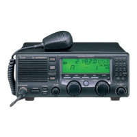
■ Ground connection
The transceiver and antenna tuner MUST have an
adequate ground connection. Otherwise, the overall
efficiency of the transceiver and antenna tuner instal-
lation will be reduced. Electrolysis, electrical shocks
and interference from other equipment could also
occur.
For best results, use the heaviest gauge wire or strap
available and make the connection as short as possi-
ble. Ground the transceiver and antenna tuner to one
ground point, otherwise voltage differences between
2 ground points may cause electrolysis.
R CAUTION: The IC-M700PRO has a negative
ground. NEVER connect the IC-M700PRO to a
“plus-grounding ship,” otherwise the transceiver
will not function.
Ground system example
Good ground points
• Ship’s ground terminal
• External ground plate
• External copper screen
Acceptable ground points
• Stainless steel tuna tower
• Stainless steel stanchion
• Through mast
• Through hull
• Metal water tank
Undesirable ground points
(these points may cause electrolysis)
• Engine block
• Keel bolt
Unusable ground points
(these connections may cause an explosion or elec-
trical shock)
• Gas or electrical pipe
• Fuel tank
• Oil-catch pan
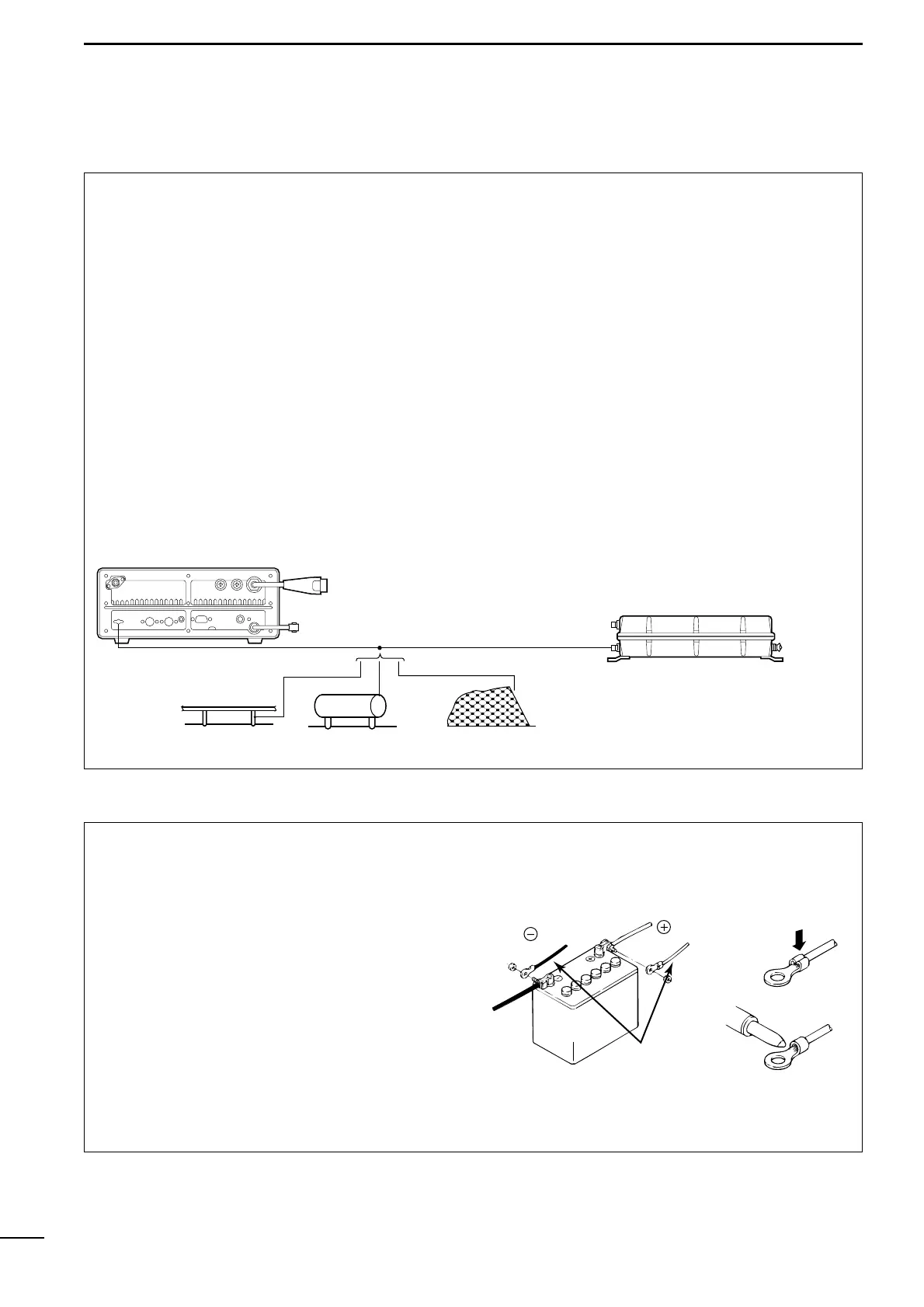
■ Power source
The transceiver requires regulated DC power of 13.6
V and at least 30 A. There are 3 ways to supply
power:
• Direct connection to a 12 V battery in your ship
through the supplied DC power cable.
• Use the PS-60
DC POWER SUPPLY
to connect to an
AC outlet.
• Use the PS-66
DC
-
DC CONVERTER
to connect to a
19–32 V DC power source.
R CAUTION: The supplied DC power cable MUST
be used to provide power to the transceiver.
AVOID exceeding the 3 m (10 ft) length of the DC
power cable. If it is necessary to make a run of
over 3 m, use #6 or similar weight cable instead of
the supplied DC power cable for a maximum run
of 6 m (20 ft).
DC power cable connection
✍ NOTE: Use terminals
for the cable connection.