6
CONNECTIONS AND INSTALLATION
21
■ Installing internal options
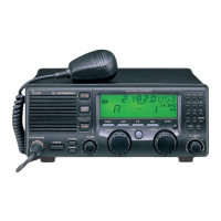
D Opening the case
Follow the case and cover opening procedures
shown here when you want to install an option or ad-
just a setting for non-Icom tuner control.
➀ Remove the 9 screws from the rear panel, then re-
move the rear frame and rear sealing.
➁ Remove the transceiver case.
➂ When reassembling the transceiver, check the fol-
lowing points:
➠ Internal fan and slits in the case are on the same
side.
➠ Front sealing is mated correctly.
➠ Rear sealing is attached in the proper orienta-
tion.
➠ Screws are tightened securely.
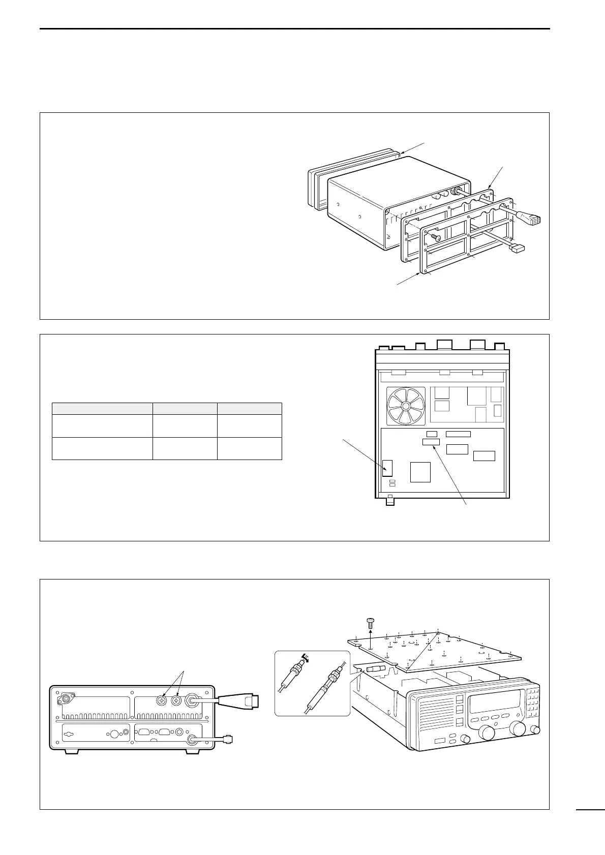
D Installing an optional filter and alarm unit
After opening the case as shown above, install the
desired option to the position as at right. These op-
tions are available (or already built-in) for the following
versions:
After installing the 2-tone alarm unit into a General
version, remove the plastic cover on the [ALARM]
switch to use the switch.
■ Fuse replacement
The transceiver has 3 fuses to protect internal cir-
cuitry, 2 fuses for the fuse holder on the rear panel
and 1 for inside. If the transceiver stops functioning,
check the fuses below.
Space for the FL-100.
(Plug in here. Right or