6
CONNECTIONS AND INSTALLATION
16
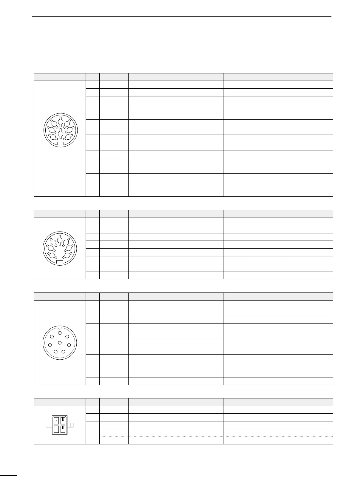
■ Connector information
ACC(1)
PIN
PIN NAME DESCRIPTION
SPECIFICATIONS
1 CWK CW and FSK keying input. Input level: Less than 0.6 V for transmit.
2 GND Connects to ground. Connected in parallel with ACC(2) pin 2.
3 SEND
Input/output pin.
Goes to ground when transmitting.
When grounded, transmits.
Ground level: –0.5 to 0.8 V
Input current: Less than 20 mA
Connected in parallel with ACC(2) pin 3.
4 MOD
Modulator input.
Usable when pin 3 is grounded.
Input impedance: 10 kΩ
Input level: Approx. 100 mV rms
5 AF
AF detector output.
Fixed, regardless of [AF] position.
Output impedance: 4.7 kΩ
Output level: 100–300 mV rms
6 NC No connection.
7 13.6 V 13.6 V output when power is on.
Output current: Max. 1 A
Connected in parallel with ACC(2) pin 7.
8 ALC ALC voltage input.
Control voltage: –3 to 0 V
Input impedance: More than 10 kΩ
Connected in parallel with ACC(2) pin 5.
2
8
45
13
67
ACC(2)
PIN
PIN NAME DESCRIPTION
SPECIFICATIONS
2 GND Same as ACC(1) pin 2.
3 SEND Same as ACC(1) pin 3.
1 8 V Regulated 8 V output.
Output voltage: 8 V ±0.3 V
Output current: Less than 10 mA
4 NC No connection.
5 ALC Same as ACC(1) pin 8.
6 RLC T/R relay control output. When transmitting: 0 V (less than 0.5 A)
7 13.6 V Same as ACC(1) pin 7.
2
45
13
67
MICROPHONE PIN NAME DESCRIPTION
SPECIFICATIONS
2 NC No connection.
1 MIC+
Audio input from the microphone
element.
Input impedance: 600 Ω
4 AF2
AF input.
Connected to pin 3 in the microphone.
5 PTT PTT switch input. When grounded, transmits.
6 GND Connected to ground.
3 AF1
AF output controlled with [VOLUME].
Connected to pin 4 in the microphone.
Output impedance: 4 Ω
7 MIC– Coaxial ground for MIC+.
8 AF– Coaxial ground for AF1 and AF2.
1
7
6
54
3
8
2
PIN
TUNER PIN NAME DESCRIPTION
SPECIFICATIONS
1 KEY Key signal input. –0.5–0.8 V during tuning
4
E
ANTC
–ve terminal
Antenna current input
For USA version
Input level: Approx. 2 Vrms (Europe version)
2 START Start signal output. Pulled up 8 V, 0 V(100 msec) as start signal.
3 13.6V 13.6 V output Max. current: 2 A
12
34
PIN