6
CONNECTIONS AND INSTALLATION
19
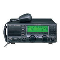
■ Antenna
Most stations operate with a whip or long wire (insu-
lated backstay) antenna. However, these antennas
cannot be connected directly to the transceiver since
their impedance may not be matched with the trans-
ceiver antenna connector.
With a 50 Ω matched antenna all marine bands can-
not be used. The following antenna matcher or an-
tenna tuner may be helpful for antenna installation.
D MN-100/MN-100L ANTENNA MATCHERS
D AT-130 AUTOMATIC ANTENNA TUNER
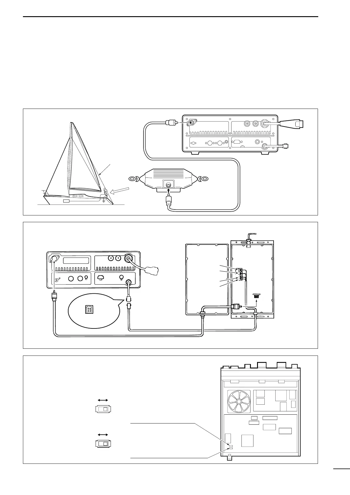
D Non-Icom tuner
Some non-Icom tuners may be used with the IC-
M700PRO. Please consult your dealer or marina if
you wish to connect one. The following internal set-
tings may be required for connection.
Supplies 8 V when push-
ing [TUNE].
Grounded when pushing [TUNE].
(used for AT-130—default)
Accepts “HIGH” as an answer back signal.
(used for AT-130—default)
Accepts “LOW” as an an-
swer back signal.