DESCRIPTION OF AIRPLANE AND SYSTEMS / INSTRUMENT PANELS 7-11
CHANGE A2 ICON A5-B / PILOT’S OPERATING HANDBOOK
CHAPTER 7
(5) Pitch trim position indicator with markings for DOWN, T/O and
UP
(6) Strobe light switch
(7) Nav light switch
(8) Taxi light switch
(9) Landing light switch
(10) Bilge pump switch with indicator light for ON
(11) Heater control
(12) Water rudder control with indicator light for EXT (water rudder
extended)
(13) Engine throttle control
(not shown) Hour meter located beneath the center arm rest
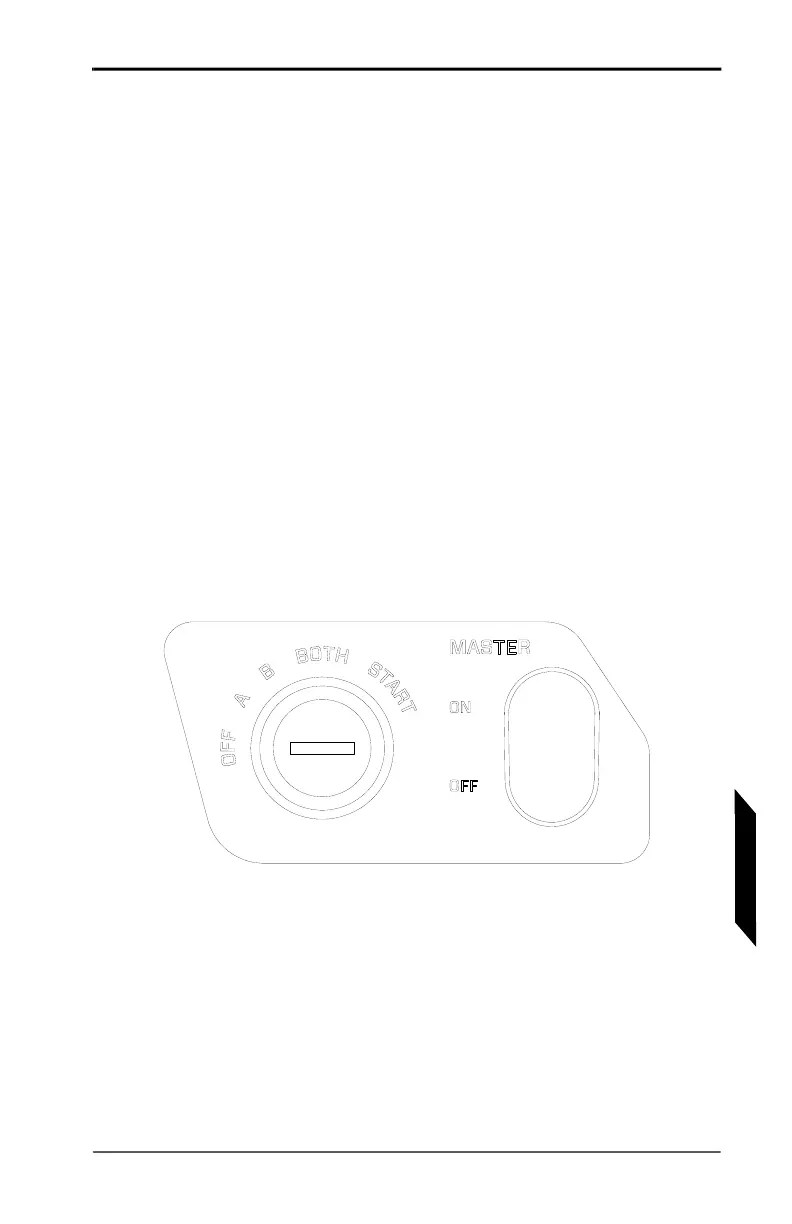
7.5.3 MASTER SWITCH AND KEY
FIGURE 7-3
MASTER SWITCH AND KEY PANEL
The master switch and key panel is located to the lower left of the
flight instrument cluster. It contains the key switch for selecting
between ‘A’ and ‘B’ and ‘BOTH’ on the engine electrical and control
systems as well as engaging the starter. The master switch is the
main electrical switch for the entire aircraft electrical system.
NOTE: In the event it becomes necessary to turn off
the master switch in flight, the engine will
continue to run.