DESCRIPTION OF AIRPLANE AND SYSTEMS / INSTRUMENTS 7-13
CHANGE A2 ICON A5-B / PILOT’S OPERATING HANDBOOK
CHAPTER 7
Kelly Manufacturing Company Publication 1404 for the KMC
2000-2 digital attitude indicator.
NOTE: The magnetic direction indicator can be
re-calibrated using the procedure detailed in
the A5-B Maintenance Manual.
Instruments used for engine and fuel monitoring form the
Secondary Cluster along the bottom row of the stack. These include
the fuel quantity (4), tachometer (5), oil temperature (6), oil pressure
(7), and water/coolant temperature (8) gauges. All secondary
instruments contain a red LED light that will illuminate whenever a
redline limit is reached.
An annunciator panel (10) is located near the center of the
instrument console between the Primary Cluster and Secondary
Cluster. (See “Annunciator Panel” on page 7-14.)
Not shown in the figure is the panel dimmer knob which is just below
the water/coolant temperature gauge (8). The dimmer is used for
adjusting the brightness of the instrument lighting.
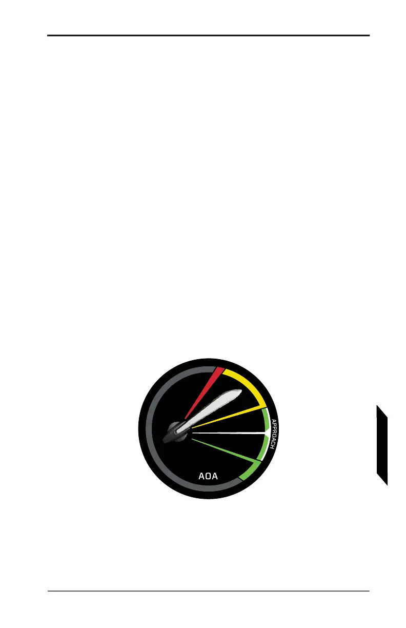
7.6.2 ANGLE OF ATTACK SYSTEM
FIGURE 7-5
AOA GAUGE WITH A MID-YELLOW INDICATION
The AOA gauge provides a visual indication of how hard the wing is
working to generate lift and how much more lift it can supply at any
given time. AOA is related to stick position, and so the AOA gauge
can also provide an approximate indication of the current stick
position and how much farther aft it can move before the wing will
stall.