7-12 DESCRIPTION OF AIRPLANE AND SYSTEMS / INSTRUMENTS
ICON A5-B / PILOT’S OPERATING HANDBOOK CHANGE A2
CHAPTER 7
7.6 INSTRUMENTS
7.6.1 GENERAL INFORMATION
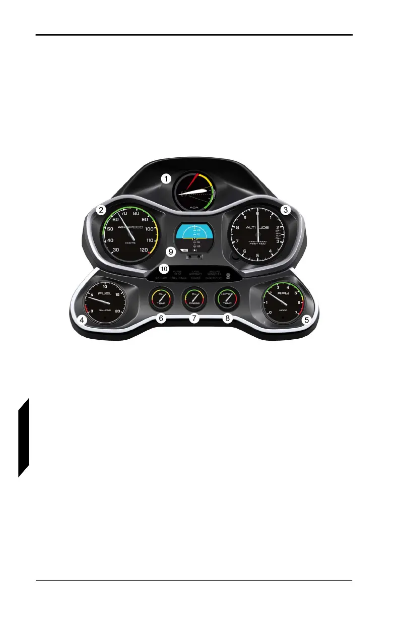
FIGURE 7-4
INSTRUMENT STACK
The flight, engine, and fuel instruments in the A5-B have been
located according to their priority for controlling the aircraft. The
most prominent instruments used for aircraft control form the
Primary Cluster across the top of the instrument stack. These
include the angle of attack (AOA) gauge (1), airspeed indicator (2),
and altimeter (3). The AOA gauge collects data from ports located
on the leading edge of the left wing. The face of the gauge
incorporates a unique ICON design employing green, yellow, and red
segments to clearly indicate available lift margin above stall at all
times. The airspeed indicator and altimeter are standard analog
gauges connected to the pitot-static system.
A digital attitude indicator (AI)(9) is centrally located for simple
reference in the middle of the instrument panel, providing aircraft
pitch information to ±30°, bank to ±60°, and magnetic direction
indication. The AI includes two buttons just below that will dim (left
button) or brighten (right button) the display screen when pressed
individually. Pressing and holding both buttons simultaneously
changes screen modes. For more details on operating the AI, see