Single Stage Multi Position Furnace
Service
Manual
42
440 08 2001 02
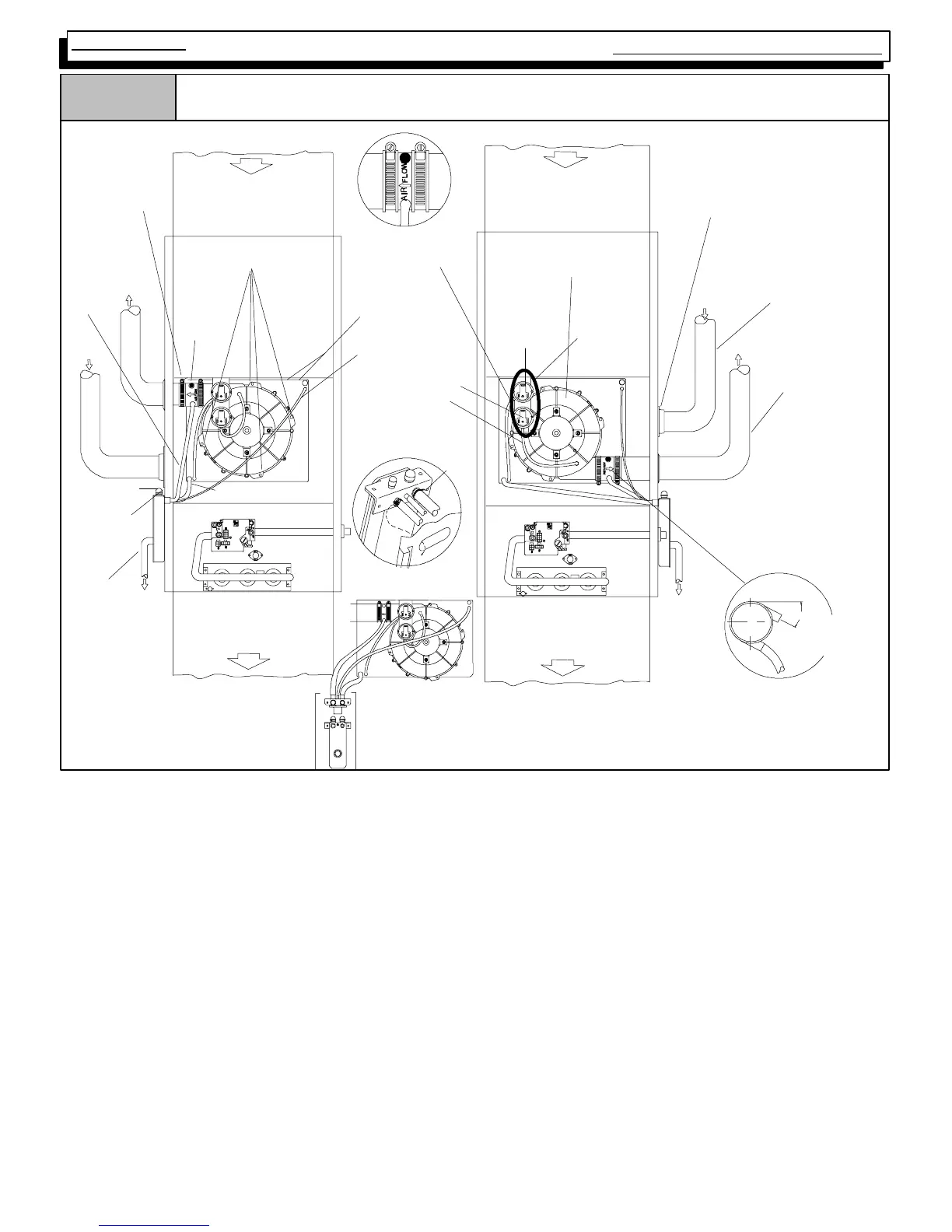
Figure 50
Downflow Installations (Single Pipe & Direct Vent N9MP1 & N9MP2 --A2 Models)
Vent Pipe
Vent Pipe
Grommet
Vent Fitting
&Clamps
dwg 25-- 23--60
Return Air
Drain Line
Pressure
Switch,
Transition
Pressure Switch
Hose, Transition
Yellow
Plastic
Cap
Plastic
Caps
Condensate
Trap & Gasket
3
/
4
²
²²
² Hose & Clamps
Supply Air
5
/
8
²
²²
² Hose &
Clamps
Exhaust
Plastic Caps
Exhaust
Return Air
RIGHT Side Venting
LEFT Side Ve nting
Combustion Blower
(Rotate 180°
°°
° for Left Side)
Supply Air
Transition Box
Pressure Switch
Hose, Blower
Pressure
Switch, Blower
DRAIN SIDE VIEW
Rotate
downward
20°
°°
° to 30°
°°
°
Inlet
Inlet
Combustion
Air Pipe,
N9MP2 ONLY
Combustion Blower
Mounting Screws (4)
Some Models
have one
pressure switch
Preassemble &
insert into furnace
Trap Connection
“Clamp ears”
Pointed
OUT
AIR FLOW
NOTE: TRAP MUST BE PRIMED BEFORE OPERATION
Downflow Installations - (Single Pipe & Direct Vent N9MP1 & N9MP2 Models) (See Figure 50)
Note: For easier installation of the drain hoses and clamps to the
condensate trap, follow the directions outlined below except do not
make any clamp connections to any of the drain stubs and hoses
until the hose routing and lengths have been determined. Remove
the condensate trap and drain hoses from the furnace and secure
the drain hoses to the drain stubs on the trap with the hose clamps
(position the clamps as shown in Figure 50). Install the condensate
trap/hose assembly to the furnace casing. Hook one side of the
“clamp ears” on the drain stub through the hole in the casing and
push the condensate trap into position. Secure with the two screws.
Reconnect the drain hoses to the stubs on the vent fitting and the
plastic transition and secure with the clamps.
Mount the condensate drain trap in a vertical position to either the
right or left side of the furnace using the two screws and gasket that
are provided. If needed, remove the hole plugs from the furnace
side panel and relocated to the open set of holes in the oppositeside
panel.
NOTE: All gaskets and seals must be in place for sealed combus-
tion applications.
Ensure that the vent fitting is securely attached to the combustion
blower using the rubber coupling and clamps.
This configuration allows right side venting from the furnace. If the
left side venting is required, the combustion blower must be relo-
cated on the plastic transition box. Remove the four(4) screws that
secure the blower to the transition. Rotate the blower 180° and se-
cure with the four(4) screws. Use caution to not over tighten the
screws to prevent stripping out of the plastic mounting holes.
NOTE: The vent fitting MUST be installed with the airflow marking
arrow pointed toward the vent pipe, with the drain stub at a 20° to 30°
downward slope.
Plug the upper drain stub on the vent fitting with the yellow plastic
cap.
Remove the pressure switch hose from the upper stub on theplastic
transition box.
Relocate the plastic caps on the stubs of the plastic transition box
from the lower stubs to the upper stubs and secure tightly with the
clamps.
Route the pressure switch hose to the lower stub on the plastic tran-
sition box. Cut off excess hose and discard. Connect the pressure
switch hose to the lower stub on the plastic transition box. NOTE:
Failure to correctly install the pressure switch hose to the transition
box can adversely affect the safety control operation.