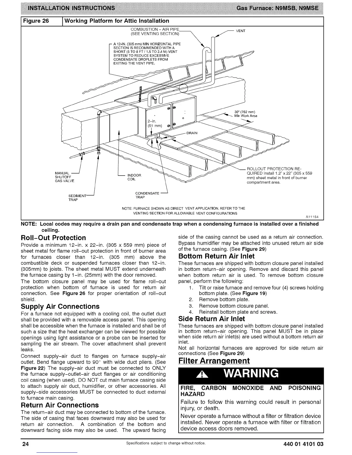
Figure 26 I Working Platform for Attic Installation
COMBUSTION - AIR PIPE VENT
(SEE VENTING SECTION)
(305 mm) MIN HORIZONTAL PIPE
SECTION IS RECOMMENDED WITH A
SHORT (5 TO 8 FT / 1.5 TO 2.4 M) VENT
SYSTEM TO REDUCE EXCESSIVE
CONDENSATE DROPLETS FROM
EXITING THE VENT PIPE.
30" (762 mm)
Min Work Area
INDOOR
COIL
CONDENSATE
TRAP
ROLLOUT PROTECTION RE-
QUIRED Install 1.2" x 22" (305 x 559
mm) sheet metal in front of burner
compartment area.
NOTE:
ceiling.
Roll-Out Protection
Provide a minimum 12-in. x 22-in. (305 x 559 mm) piece of
sheet metal for flame roll-out protection in front of burner area
for furnaces closer than 12-in. (305 mm) above the
combustible deck or suspended furnaces closer than 12-in.
(305mm) to joists. The sheet metal MUST extend underneath
the furnace casing by 1-in. (25mm) with the door removed.
The bottom closure panel may be used for flame roll-out
protection when bottom of furnace is used for return air
connection. See Figure 26 for proper orientation of roll-out
shield.
Supply Air Connections
For a furnace not equipped with a cooling coil, the outlet duct
shall be provided with a removable access panel. This opening
shall be accessible when the furnace is installed and shall be of
such a size that the heat exchanger can be viewed for possible
openings using light assistance or a probe can be inserted for
sampling the air stream. The cover attachment shall prevent
leaks.
Connect supply-air duct to flanges on furnace supply-air
outlet. Bend flange upward to 90° with wide duct pliers. (See
Figure 22) The supply-air duct must be connected to ONLY
the furnace supply-outlet-air duct flanges or air conditioning
coil casing (when used). DO NOT cut main furnace casing side
to attach supply air duct, humidifier, or other accessories. All
supply-side accessories MUST be connected to duct external
to furnace main casing.
Return Air Connections
The return-air duct may be connected to bottom of the furnace.
The side of casing that faces downward may also be used for
return air connection. A combination of the bottom and
downward facing side may also be used. The upward facing
NOTE: FURNACE SHOWN AS DIRECT VENT APPLICATION. REFER TO THE
VENTING SECTION FOR ALLOWABLE VENT CONFIGURATIONS
A1ff54
Local codes may require a drain pan and condensate trap when a condensing furnace is installed over a finished
side of the casing cannot be used as a return air connection.
Bypass humidifier may be attached into unused return air side
of the furnace casing. (See Figure 29)
Bottom Return Air Inlet
These furnaces are shipped with bottom closure panel installed
in bottom return-air opening. Remove and discard this panel
when bottom return air is used. To remove bottom closure
panel, perform the following:
1. Tilt or raise furnace and remove four (4) screws holding
bottom plate. (See Figure 19)
2. Remove bottom plate.
3. Remove bottom closure panel.
4. Reinstall bottom plate and screws.
Side Return Air Inlet
These furnaces are shipped with bottom closure panel installed
in bottom return-air opening. This panel MUST be in place
when side return air inlet(s) are used without a bottom return air
inlet.
Not all horizontal furnaces are approved for side return air
connections (See Figure 29)
Filter Arrangement
FIRE, CARBON MONOXIDE AND POISONING
HAZARD
Failure to follow this warning could result in personal
injury, or death.
Never operate a furnace without a filter or filtration device
installed. Never operate a furnace with filter or filtration
device access doors removed.
24 specificationssubjectto change without notice. 440 01 4101 03