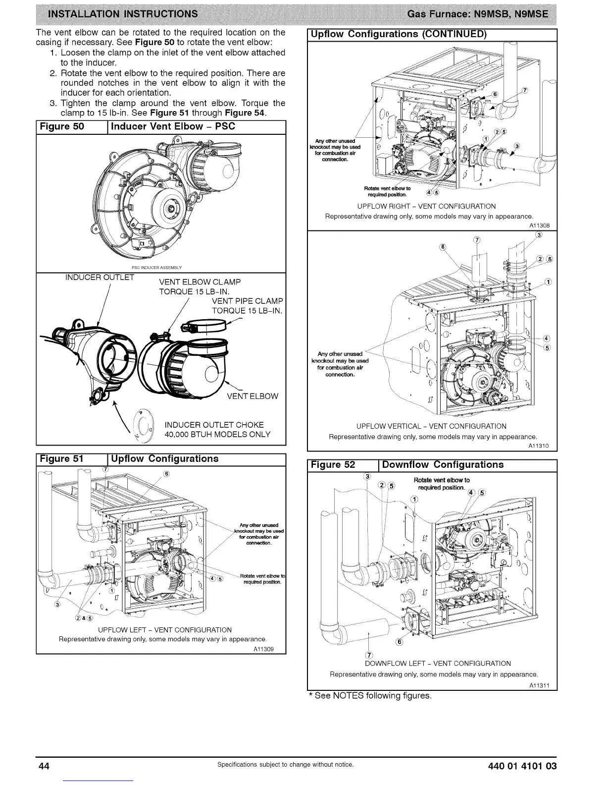
The vent elbow can be rotated to the required location on the
casing if necessary. See Figure 50 to rotate the vent elbow:
1. Loosen the clamp on the inlet of the vent elbow attached
to the inducer.
2. Rotate the vent elbow to the required position. There are
rounded notches in the vent elbow to align it with the
inducer for each orientation.
3. Tighten the clamp around the vent elbow. Torque the
clamp to 15 Ib-in. See Figure 51 through Figure 54.
Figure 50 1Inducer Vent Elbow - PSC
/i'
Y
PSC INDUCER ASSEMBLY
INDUCER OUTLET
VENT ELBOW CLAMP
TORQUE 15 LB-IN.
VENT PIPE CLAMP
TORQUE 15 LB-IN.
Figure 51
\
VENT ELBOW
INDUCER OUTLET CHOKE
40,000 BTUH MODELS ONLY
Upflow Configurations
Any _ _used
for cecnbustten air
o_r_actten.
" - Rotate vent elbow to
required position.
d2b_®
UPFLOW LEFT - VENT CONFIGURATION
Representative drawing only, some models may vary in appearance.
Al1309
Upflow Configurations (CONTINUED)
Anyotherunused
le'u_kentmay bo used
for combustionair
cennec_en.
Rotate vent elbow to
require_:l posi_en.
UPFLOW RIGHT - VENT CONFIGURATION
Representative drawing only, some models may vary in appearance.
Al1308
J
J
/
/
j/-_/J
Any other unused <z
knockout may be used tlI
for combustion air ',
connection.
,, 0
\\\
UPFLOW VERTICAL - VENT CONFIGURATION
Representative drawing only, some models may vary in appearance.
Al1310
Figure 52 I Downflow Configurations
_3_ Rotate ventelbowto
i F, ,_ F,,_,
......... ! _2__5_ required position.
/ ...........
I
@
DOWNFLOW LEFT - VENT CONFIGURATION
Representative drawing only, some models may vary in appearance.
Al1311
* See NOTES following figures.
44 specificationssubjectto change without notice. 440 01 4101 03