Downflow Configurations (CONTINUED)
Rotate vent elbow to
required position,
DOWNFLOW RIGHT - VENT CONFIGURATION
Representative drawing only, some models may vary in appearance.
Alt3t2
DOWNFLOW VERTICAL - VENT CONFIGURATION
Requires Accessory Internal Vent Kit
See Specification Sheets for current kit number
Representative drawing only, some models may vary in appearance.
L11F063
* See NOTES following figures.
Figure 53 _Horizontal Left Configurations
AI1327
HORIZONTAL LEFT - VERTICAL VENT CONFIGURATION
Representative drawing only, some models may vary in appearance.
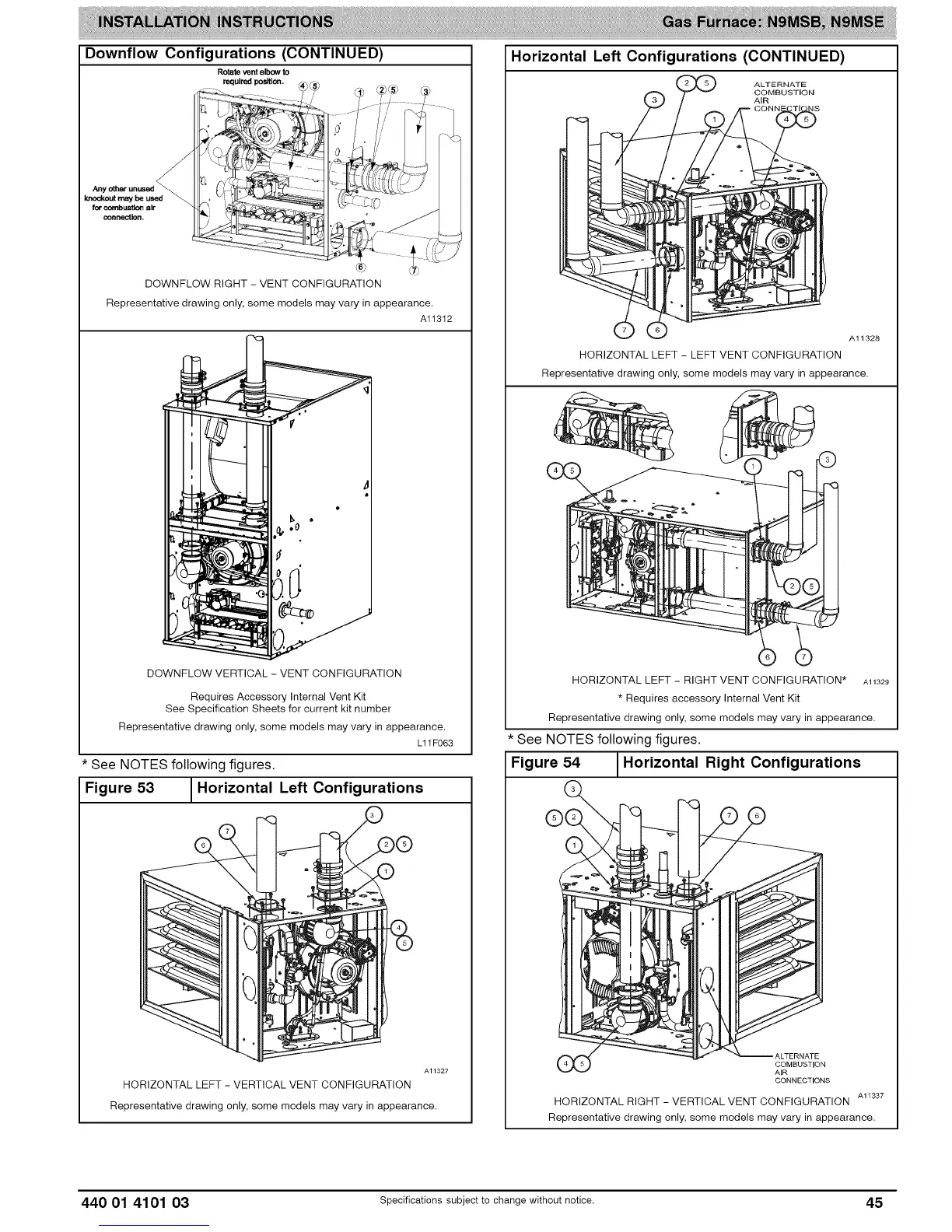
Horizontal Left Configurations (CONTINUED)
ALTERNATE
COMBUSTION
AIR
A11328
HORIZONTAL LEFT - LEFT VENT CONFIGURATION
Representative drawing only, some models may vary in appearance.
I
©
HORIZONTAL LEFT - RIGHT VENT CONFIGURATION* Al1329
* Requires accessory Internal Vent Kit
Representative drawing only, some models may vary in appearance.
* See NOTES following figures.
Figure 54 1Horizontal Right Configurations
COMBUSTION
CONNECTIONS
AI 1337
HORIZONTAL RIGHT - VERTICAL VENT CONFIGURATION
Representative drawing only, some models may vary in appearance.
440 01 4101 03 Specificationssubjectto change without notice. 45