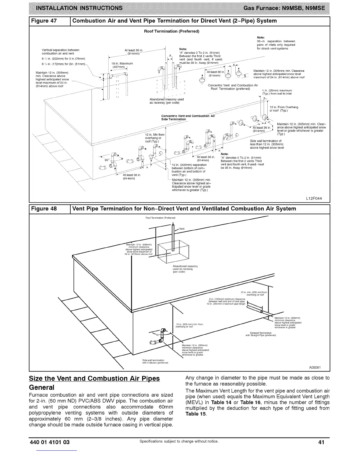
Figure47 _Combustion Air and Vent Pipe Termination for Direct Vent (2-Pipe) System
Vertical separation between
combustion air and vent
8 ;,_ in (222mm) for 3 in (76ram)
6 in. (172mm) for 2in. (51mm) ,
,\
\,
Maintain 12 in (305mm) \\
min. Clearance above
highest anticipated snow
level maximum of 24 in.
(614mm) above roof
\\\\\
Roof Termination (Preferred)
J
A east36 n ............ q
................ (914mm) ....... / I'A4
I /
18 in. Maximum
Note:
"A" denotes 0 To 2 in (51 mm)
Between the first 2 vents Third
vent (and fourth vent, if used)
must be 36 in Away (914mm)
Note:
36-in separation between
pairs of inlets only required
for direct-vent systems
Maintain 12 in. (3O5mm) min Clearance
above highest anticipated snow level
maximum of 24 in. (614ram) above roof
(914mm)
i
i
Abandoned masonry used
as raceway (per code)
Concentric Vent and Combustion Air
Roof Termination (preferred)
Concentric Vent and Combustion Air
Side Termination
12 in. Min from
overhang or _
roof (Typ.)
1 in (25mm) maximum
(Typ.) from wall to inlet
12 in. From Overhang
or roof (Typ.)
(914rain)_
/ ....
Maintain 12 in (3O5mm) min Clear-
ance above highest anticipated snow
level or grade whichever is greater
(Typ)
Side wall termination of
less than 12 in (3O5mm)
above highest snow level
(914mm)
(305ram) separation
between bottom of com-
bustion air and bottom of
vent (Typ.)
Maintain 12 in. (305mm) rain.
Clearance above highest an-
ticipated snow level or grade
whichever is greater (Typ)
Note:
"A" denotes 0 To 2 in (51ram)
Between the first 2 vents Third
vent (and fourth vent, if used) must
be 36 in. Away (914mm)
L12F044
Figure 48
Vent Pipe Termination for Non-Direct Vent and Ventilated Combustion Air System
Roof Termination (Preferred)
Maintain 12 in (3O5mm)
minimum clearance
above highest anticipated
snow level maximum of
24 _n (61 gram) above roof
Abandoned masonry
used as raceway
(percode)
12 in rain (305 ram)from
overhang or roof
6 in 152mm) minimum clearance
bergen wa I and end o vent pipe
10 in (254mm) m_lmum pipe lengh
Maintain 12in (3O5mm)
minimum clearance
above highest anticipated
whichever is greater
Sidewall Termination
w_th Straight P_pe (preferred)
Side wall terminaSon
w_h 2 elbows (preferred)
Maintain 12 in (3O5mm)
minimum clearance
above highest anticipated
snow level or grade
whichever _s greater
A05091
Size the Vent and Combustion Air Pipes
General
Furnace combustion air and vent pipe connections are sized
for 2-in. (50 mm ND) PVC/ABS DWV pipe. The combustion air
and vent pipe connections also accommodate 60mm
polypropylene venting systems with outside diameters of
approximately 60 mm (2-3/8 inches). Any pipe diameter
change should be made outside furnace casing in vertical pipe.
Any change in diameter to the pipe must be made as close to
the furnace as reasonably possible.
The Maximum Vent Length for the vent pipe and combustion air
pipe (when used) equals the Maximum Equivalent Vent Length
(MEVL) in Table 14 or Table 16, minus the number of fittings
multiplied by the deduction for each type of fitting used from
Table 15.
440 01 4101 03 Specificationssubjectto change without notice. 41