NOTE: Use AWG No. 18 color-coded copper thermostat wire
for lengths up to 100 ft. (30.5 M). For wire lengths over 100 ft.,
use AWG No. 16 wire.
The 24-v circuit contains an automotive-type, 3-amp. fuse
located on the control. Any direct shorts during installation,
service, or maintenance could cause this fuse to blow. If fuse
replacement is required, use ONLY a 3-amp. fuse of identical
size. (See Figure 40)
See the Service and Technical Support manual for detailed
instructions on control wiring and setup,
Thermostats and Control Settings for
N9MSB & N9MSE Single-Stage Furnaces
A single stage heating and single-stage cooling thermostat
may be used with the furnace. Refer to typical thermostat wiring
diagrams and the Sequence of Operation section of the
Service and Technical Support manual for details on
configuring the furnace control board. Consult the thermostat
installation instructions for specific information about
configuring the thermostat.
Accessories (See Figure 39 and/or Figure 40)
1. Electronic Air Cleaner (EAC):
Connect an accessory Electronic Air Cleaner (if used)
using 1/4-in female quick connect terminals to the two
male 1/4-in quick-connect terminals on the control
board marked EAC and NEUTRAL. The terminals are
rated for 115 VAC, 1.0 amps maximum and are
energized during blower motor operation. (See
Figure 40)
2. Humidifier (HUM 24VAC and HUM)
• a. HUM 24VAC: Connect an accessory 24 VAC, 0.5
terminal on the control board thermostat strip. The
HUM 24VAC terminal is energized when there is a call
for heat (W) and the pressure switch (LPS) closes.
(See Figure 40)
• b. HUM: Connect an accessory 115VAC (EAC and
HUM are 1 amp maximum combined) humidifier (if
used) to the ¼-inch male quick connect HUM terminal
and NEUTRAL ¼-inch quick connect. The HUM
terminal is energized when the inducer motor is
energized (IDR). (See Figure 40)
NOTE: A field-supplied, 115-v controlled relay connected to
EAC terminals may be added if humidifier operation is desired
during blower operation.
NOTE: DO NOT connect furnace control HUM 24VAC terminal
to H (humidifier) terminal on humidity sensing thermostat, or
similar device. See humidity sensing thermostat, thermostat, or
controller manufacturer's instructions for proper connection.
Alternate Power Supplies
This furnace is designed to operate on a utility generated
power which has a smooth sinusoidat waveform. If the furnace
is to be operated on a generator or other alternate power
supply, the alternate power supply must produce a smooth
sinusoidal waveform for compatibility with furnace electronics.
The alternate power supply must generate the same voltage,
phase, and frequency (Hz) as shown in Table 11 or on the
furnace rating plate.
Power from an alternate power supply that non-sinusoidat may
damage the furnace or cause erratic furnace operation.
amp maximum humidifier (if used) to the 1/4-in mate
quick-connect HUM 24VAC terminal and C screw
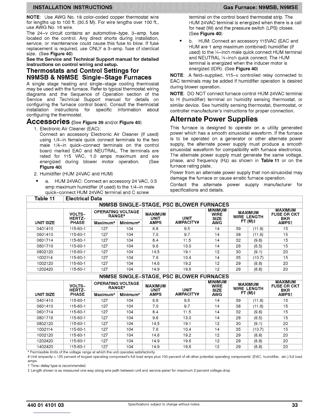
Table 11 Electrical Data
UNIT SIZE
0401410
0601410
0601714
0801716
0802120
1002114
1002120
1202420
Contact the alternate power supply manufacturer for
specifications and details.
VOLTS-
HERTZ-
PHASE
115-60-1
115-60-1
115-60-1
115-60-1
115-60-1
115-60-1
115-60-1
115-60-1
N9MSB SINGLE-STAGE, PSC BLOWER FURNACES
OPERATINGVOLTAGE MINIMUM
RANGE* MAXIMUM WIRE
UNIT UNIT SIZE
Maximum* Minimum* AMPS AMPACITY# AWG
6.8
7.0
8.4
9.6
14.5
7.6
14.6
14.9
9.5
9.7
11.5
13.0
19.1
10.4
19.2
19.6
14
14
14
14
12
14
12
12
MAXIMUM
WIRE LENGTH
FT (i)_
39 (11.9)
38 (11.6)
32 (9.8)
28 (8.5)
30 (9.1)
35 (10.7)
29 (8.8)
29 (8.8)
127 104
127 104
127 104
127 104
127 104
127 104
127 104
127 104
MAXIMUM
FUSE OR CKT
BKR
AMPSt
15
15
15
15
20
15
20
20
UNIT SIZE
0401410
0601410
0601714
0801716
0802120
1002114
1002120
1202420
1402420
VOLTS-
HERTZ-
PHASE
115-60-1
115-60-1
115-60-1
115-60-1
115-60-1
115-60-1
115-60-1
115-60-1
115-60-1
N9MSE SINGLE-STAGE, PSC BLOWER FURNACES
OPERATING VOLTAGE
RANGE*
Maximum* Minimum*
127 104
127 104
127 104
127 104
127 104
127 104
127 104
127 104
127 104
MAXIMUM
UNIT
AMPS
6.8
7.0
8.4
9.6
14.5
7.6
14.6
14.9
14.9
UNIT
AMPAClTY#
9.5
9.7
11.5
13.0
19.1
10.4
19.2
19.6
19.6
MINIMUM
WIRE
SIZE
AWG
14
14
14
14
12
14
12
12
12
Permissible limits of the voltage range at which the unit operates satisfactorily.
MAXIMUM
WIRE LENGTH
FT (i)$
39 (11.9)
38 (11.6)
32 (9.8)
28 (8.5)
30 (9.1)
35 (10.7)
29 (8.8)
29 (8.8)
29 (8.8)
MAXIMUM
FUSE OR CKT
BKR
AMPSt
15
15
15
15
20
15
20
20
20
# Unit ampacity = 125 percent of largest operating component's full load amps plus 100 percent of all other potential operating components' (EAC, humidifier, etc.) full load
amps.
1-Time-delay type is recommended.
$ Length shown is as measured one way along wire path between unit and service panel for maximum 2 percent voltage drop.
440 01 4101 03 Specifications subject to change without notice. 33