8. Electrical Wiring
Electrical shock hazard.
Turn OFF electrical power at fuse box or service panel
before making any electrical connections and ensure a
proper ground connection is made before connecting
line voltage.
Failure to do so can result in death, personal injury
and/or property damage.
PowerSupplyWiring
The furnace MUST be electrically wired and grounded in accor-
dance with local codes, or in the absence of local codes, the appli-
cable national codes.
Field wiring connections must be made inside the furnace con-
nection box. A suitable strain relief should be used at the point the
wires exit the furnace casing.
Copper conductors shall be used. Line voltage wires should be
sized for the input amps stated on the rating plate. Furnace must
be connected to its own separate circuit.
Thermostat
Thermostat location has an important effect on the operation of
the unit. Follow instructions included with thermostat for correct
mounting and wiring.
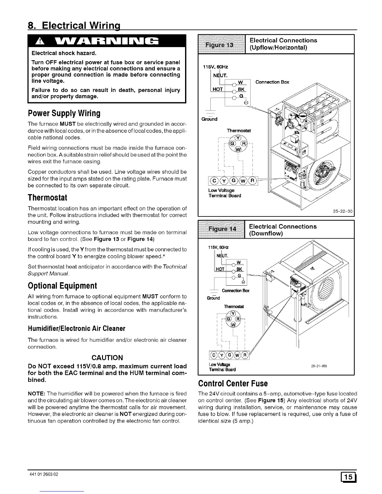
Low voltage connections to furnace must be made on terminal
board to fan control. (See Figure 13 or Figure 14)
If cooling is used, the Y from the thermostat must be connected to
the control board Y to energize cooling blower speed.*
Set thermostat heat anticipator in accordance with the Technical
Support Manual.
OptionalEquipment
All wiring from furnace to optional equipment MUST conform to
local codes or, in the absence of local codes, the applicable na-
tional codes. Install wiring in accordance with manufacturer's
instructions.
Humidifier/ElectronicAir Cleaner
The furnace is wired for humidifier and/or electronic air cleaner
connection.
CAUTION
Do NOT exceed 115V/0,8 amp, maximum current load
for both the EAC terminal and the HUM terminal com-
bined.
NOTE: The humidifier will be powered when the furnace is fired
and the circulating air blower comes on. The electronic air cleaner
will be powered anytime the thermostat calls for air movement.
However, the electronic air cleaner is NOT energized during con-
tinuous fan operation controlled by the electronic fan control.
Electrical Connections
(Upflow/Horizontal)
115V, 60Hz
NEUT.
Connection Box
Ground
Thermostat
i i
I i ! _ I
--q I I I
Low Voltage
Termina_Board
25-22-30
115V, 60Hz
NEUT.
Electrical Connections
(Downflow)
Ground
LowVoltage
TerminalBoard
25-21-05b
Control Center Fuse
The 24V circuit contains a 5-amp, automotive-type fuse located
on control center. (See Figure 15) Any electrical shorts of 24V
wiring during installation, service, or maintenance may cause
fuse to blow. If fuse replacement is required, use only a fuse of
identical size (5 amp.)
44101260302 [_
 Loading...