2.
With filter rack pushed back, insert front end with 1/4" flange
into position and push into front slot. with filter rack pushed as
far forward as it will go, bend 1/4" flange and 3/4" flange up
90°. See Figure 22.
NOTE: Plenum must be fitted as close to the return air flange of
the unit as possible to eliminate any air bypassing the filters.
NOTE: If filters are installed in the plenum with the filter rack pro-
vided use two 16" x 18" high velocity filters. Otherwise consult fil-
ter section of the "User's Information Manual" for proper size.
Figure 22 Filter Rack Installation
25-21-05c
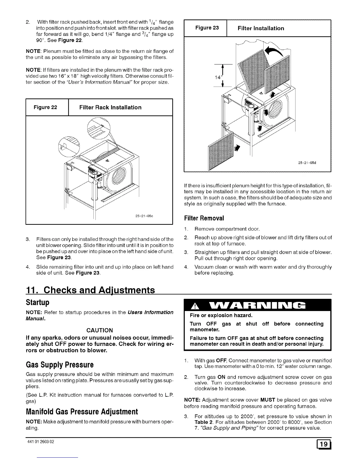
3. Filters can only be installed through the right hand side of the
unit blower opening. Slide filter into unit until it is in position to
be pushed up and over into place on the left hand side of unit.
See Figure 23.
4. Slide remaining filter into unit and up into place on left hand
side of unit. See Figure 23.
Figure 23 Filter Installation
25-21-05d
If there is insufficient plenum height for this type of installation, fil-
ters may be installed in any accessible location in the return air
system. In such a case, the filters should be of adequate size and
style as originally supplied with the furnace.
Filter Removal
1. Remove compartment door.
2. Reach up above right side of blower and lift dirty filters out of
rack at top of furnace.
3. Straighten up filters and pull straight down at side of blower.
Pull out through right door opening.
4. Vacuum clean or wash with warm water and dry thoroughly
before replacing.
11. Checks and Adjustments
Startup
NOTE: Refer to startup procedures in the Users Information
Manual.
CAUTION
If any sparks, odors or unusual noises occur, immedi-
ately shut OFF power to furnace. Check for wiring er-
rors or obstruction to blower.
Fire or explosion hazard.
Turn OFF gas at shut off before
manometer.
connecting
Failure to turn OFF gas at shut off before connecting
manometer can result in death and/or personal injury.
Gas SupplyPressure
Gas supply pressure should be within minimum and maximum
values listed on rating plate. Pressures are usually set by gas sup-
pliers.
(See L.R Kit instruction manual for furnaces converted to L.R
gas)
ManifoldGas PressureAdjustment
NOTE: Make adjustment to manifold pressure with burners oper-
ating.
1. With gas OFF, Connect manometer to gas valve or maniflod
tap. Use manometer with a 0 to min. 12" water column range.
2. Turn gas ON and remove adjustment screw cover on gas
valve. Turn counterclockwise to decrease pressure and
clockwise to increase.
NOTE: Adjustment screw cover MUST be placed on gas valve
before reading manifold pressure and operating furnace.
3. For altitudes up to 2000', set pressure to value shown in
Table 2. For altitudes between 2000' to 8000', see Section
7. "Gas Supply and Piping" for correct pressure value.
44101 260302 [_
 Loading...