HorizontalFurnaceInstallation
IMPORTANT
NOTE: Inspect unit rating plate to be certain model number be-
gins with "NTN3", "FBF', "NTG3", "NBF", "NTC6", "GNE,
"NTN6" or"NNE". This identifies unit as horizontally mountable.
If unit does NOT bear this designation, you may NOT mount this
unit horizontally. Horizontal furnace may not be mounted on
its back.
If you purchased a horizontally mountable furnace, it can be
installed horizontally in an attic, basement, crawl space, alcove,
or suspended from a ceiling in a basement or utility room in either
a right or left airflow position. See Figure 4.
iiiiiiiii%;:i¸iiiiiiiii!ii;i;i]]i]]i]]iiii;i]]]]ii;i;fill!;;!!i!i!i!i!i!i!i!ill;;;;;;;;;;;;;;;;;;;;;!
ii ii ii ii ii ii ii il ii ii ii ii ii i
Typical Horizontal Installation
The following minimum clearances to combustibles MUST be
maintained between the furnace and adjacent construction, as
shown in Figure 1. ONLY the corner of the cabinet is allowed to
contact the rafters (see Figure 4). All other clearances MUST be
observed as shown in Figure 1.
If the furnace is to be suspended from the floor joists in a crawl
space or the rafters in an attic, it is necessary to use steel pipe
straps or an angle iron frame to attach the furnace. These straps
should be attached to the furnace with sheet metal screws and to
the rafters or joists with bolts. The preferred method is to use an
angle iron frame bolted to the rafters or joists.
If the furnace is to be installed ground level in a crawl space, con-
sult local codes. A concrete pad 1" to 2" thick is recommended.
Thirty inches (30") is recommended between the front of the fur-
nace and adjacent construction or other appliances. This should
be maintained for service clearance.
Keep all insulating materials clear from Iouvered door. Insulating
materials may be combustible.
The horizontal furnaces may be installed directly on combustible
wood flooring or supports, however, it is recommended for further
fire protection cement board or sheet metal is placed between the
furnace and the combustible wood floor and extend 12" beyond
the front of the furnace louver door. (This is a recommendation
only, not a requirement).
This furnace MUST NOT be installed directly on wood flooring or
supports, carpeting, tile or other combustible material other than
wood flooring.
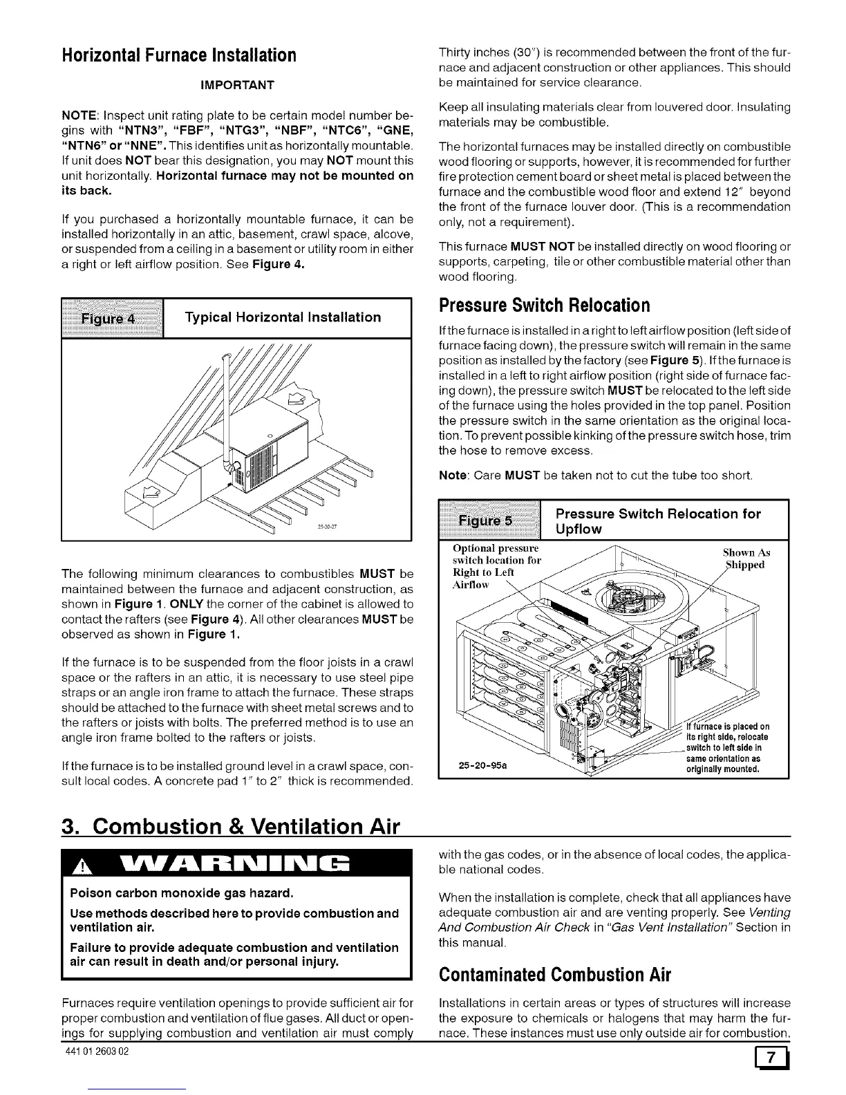
PressureSwitchRelocation
If the furnace is installed in a right to left airflow position (left side of
furnace facing down), the pressure switch wil! remain in the same
position as installed by the factory (see Figure 5). If the furnace is
installed in a left to right airflow position (right side of furnace fac-
ing down), the pressure switch MUST be relocated to the left side
of the furnace using the holes provided in the top panel. Position
the pressure switch in the same orientation as the original loca-
tion. To prevent possible kinking of the pressure switch hose, trim
the hose to remove excess.
Note: Care MUST be taken not to cut the tube too short.
iiiiiiiiiiiiiiiiiiiiiiiiiiiill¸iiiiiiiii_i%i;!iiiiiiiiiiiiii!;iiii;i;i;i;i;i;i;i;i;i;i;i;i;i;i;i;i;iiiil
iiiiiiiiiiiiiiiiiiiiiii ii i! ! ii J i ; ; i!i!i!i!i!i!i!i!i!i!i!i!i!i!i!i! !!!!i
Optional pressure
switch location for
Right to Left
Airflow
Pressure Switch Relocation for
Upflow
Shown As
25-20-95a
If furnace is placedon
itsrightside, relocate
switchto left sidein
sameorientationas
originallymounted,
3. Combustion & Ventilation Air
Poison carbon monoxide gas hazard.
Use methods described here to provide combustion and
ventilation air.
Failure to provide adequate combustion and ventilation
air can result in death and/or personal injury.
with the gas codes, or in the absence of local codes, the applica-
ble national codes.
When the installation is complete, check that all appliances have
adequate combustion air and are venting properly. See Venting
And Combustion Air Check in "Gas Vent Installation" Section in
this manual.
ContaminatedCombustionAir
Furnaces require ventilation openings to provide sufficient air for
proper combustion and ventilation of flue gases. All duct or open-
ings for supplying combustion and ventilation air must comply
44101260302
Installations in certain areas or types of structures will increase
the exposure to chemicals or halogens that may harm the fur-
nace. These instances must use only outside air for combustion.
 Loading...