Ductwork installed in attic, or exposed to outside tempera-
tures requires a minimum of 2" of insulation with outdoor type
vapor barrier.
Ductwork installed in an indoor unconditioned space re-
quires a minimum of 1" of insulation with indoor type vapor
barrier.
Filters
A filter MUST be used:
Filters are not supplied with these furnaces, but can be purchased
from your dealer.
Use either filter type:
• Washable, high velocity filters are based on a maximum air
flow rating of 600 FPM.
• Disposable, Iowvelocity filters are based on a maximum air
flow of 300 FPM when used with filter grille.
• The furnaces, with 1600 or less CFM rating use a 16" x 25"
high velocity filter. On these models the filter may be
mounted internally for bottom return using factory kit or ex-
ternally for side return.
• The furnaces with greater than 1600 CFM requires that
both !eft and right side returns are used in side return ap-
plications. Two 16" x 25" high velocity filters and racks are
provided with furnace. Filter racks must be mounted exter-
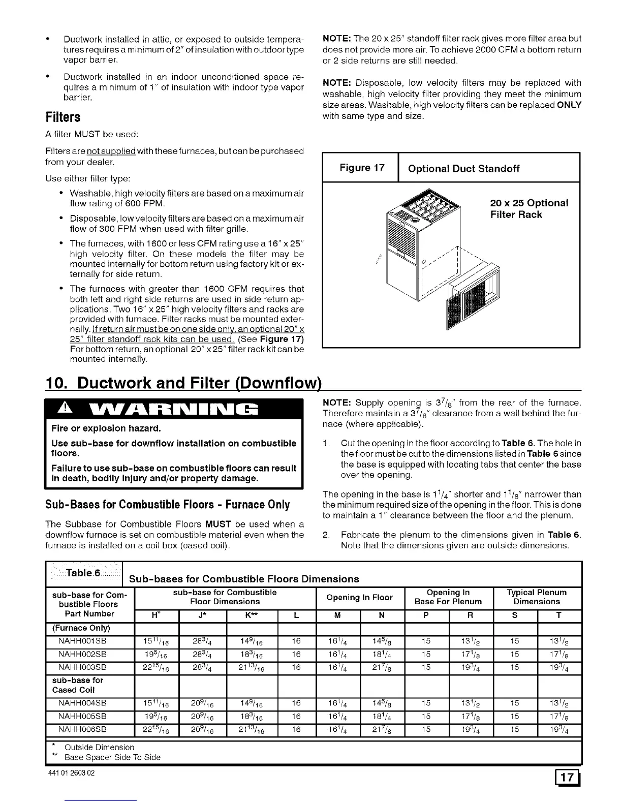
nally. !f return air must be on one side only. an optional 20" x
25" filter standoff rack kits can be used. (See Figure 17)
For bottom return, an optional 20" x 25" filter rack kit can be
mounted internally.
10. Ductwork and Filter (Downflow)
Fire or explosion hazard.
Use sub-base for downflow installation on combustible
floors.
Failure to use sub-base on combustible floors can result
in death, bodily injury and/or property damage.
Sub-Bases for CombustibleFloors - Furnace Only
The Subbase for Combustible Floors MUST be used when a
downflow furnace is set on combustible material even when the
furnace is installed on a col! box (cased col!).
NOTE: The 20 x 25" standoff filter rack gives more filter area but
does not provide more air. To achieve 2000 CFM a bottom return
or 2 side returns are still needed.
NOTE: Disposable, low velocity filters may be replaced with
washable, high velocity filter providing they meet the minimum
size areas. Washable, high velocity filters can be replaced ONLY
with same type and size.
Figure 17
1
Optional Duct Standoff
20 x 25 Optional
Filter Rack
NOTE: Supply opening is 37/8" from the rear of the furnace.
Therefore maintain a 37/8" clearance from a wall behind the fur-
nace (where applicable).
Cut the opening in the floor according to Table 6. The hole in
the floor must be cut to the dimensions listed in Table 6 since
the base is equipped with locating tabs that center the base
over the opening.
The opening in the base is 1t/4" shorter and 1t/8" narrower than
the minimum required size of the opening in the floor. This is done
to maintain a 1" clearance between the floor and the plenum.
2. Fabricate the plenum to the dimensions given in Table 6.
Note that the dimensions given are outside dimensions.
Sub-bases for Combustible Floors Dimensions
H _
15tl/16
195/16
22t5/16
15tl/16
195/I6
22t5/16
sub-base for Com-
bustible Floors
Part Number
(Furnace Only)
NAHHOOlSB
NAHHOO2SB
NAHHOO3SB
sub-base for
Cased Coil
NAHHOO4SB
NAHHOO5SB
NAHHOOSSB
* Outside Dimension
sub-base for Combustible
Floor Dimensions
J* K**
283/4 149/16
283/4 183/16
283/4 2113/16
209/16 149/I6
209/16 183/I6
209/16 2113/16
Opening In Floor
L M N
16 161/4 145/8
16 161/4 181/4
16 161/4 217/8
16 161/4 145/8
16 161/4 181/4
16 161/4 217/8
Opening In
Base For Plenum
Typical Plenum
Dimensions
15
15
15
P R
15 13t/2
15 17t/8
15 193/4
15 13t/2
15 17t/8
15 193/4
15
15
15
131/2
171/8
193/4
131/2
171/8
193/4
** Base Spacer Side To Side
44101260302
 Loading...