I Installation Instructions Combination Units I
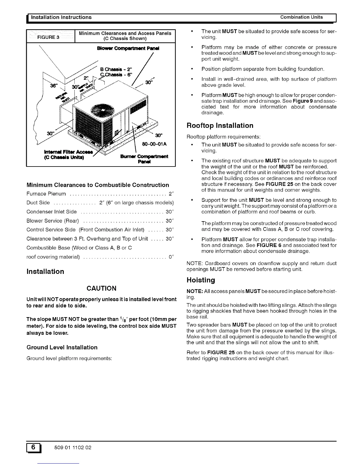
Minimum Clearances and Access Panels
FIGURE 3 (C Chassis Shown)
sk>_r _ Pmww
Bcm.+,m,:
/+++++za_'
30"
80-00-01A
Minimum Clearances to Combustible Construction
Furnace Plenum .................................... 2"
Duct Side ................ 2" (6" on large chassis models)
Condenser Inlet Side ............................... 30"
Blower Service (Rear) .............................. 30"
Control Service Side (Front Combustion Air Inlet) ...... 30"
Clearance between 3 Ft. Overhang and Top of Unit ..... 30"
Combustible Base (Wood or Class A, B or C
roof covering material) ............................... 0"
Installation
CAUTION
Unit will NOT operate properly unless it is installed level front
to rear and side to side.
The slope MUST NOT be greater than 1/8" per foot (10mm per
meter). For side to side leveling, the control box side MUST
always be lower.
Ground Level Installation
Ground level platform requirements:
The unit MUST be situated to provide safe access for ser-
vicing.
Platform may be made of either concrete or pressure
treated wood and MUST be level and strong enough to sup-
port unit weight.
Position platform separate from building foundation.
Install in well-drained area, with top surface of platform
above grade level.
Platform MUST be high enough to allow for proper conden-
sate trap installation and drainage. See Figure 9 and asso-
ciated text for more information about condensate
drainage.
Rooftop Installation
Rooftop platform requirements:
• The unit MUST be situated to provide safe access for ser-
vicing.
The existing roof structure MUST be adequate to support
the weight of the unit or the roof MUST be reinforced.
Check the weight of the unit in relation to the roof structure
and local building codes or ordinances and reinforce roof
structure if necessary. See FIGURE 25 on the back cover
of this manual for unit weights and corner weights.
• Support for the unit MUST be level and strong enough to
carry unit weight. The support may consist of a platform or a
combination of platform and roof beams or curb.
The platform may be constructed of pressure treated wood
and may be covered with Class A, B or C roof covering.
• Platform MUST allow for proper condensate trap installa-
tion and drainage. See FIGURE 6 and associated text for
more information about condensate drainage.
NOTE: Cardboard covers on downflow supply and return duct
openings MUST be removed before starting unit.
Hoisting
NOTE: All access panels MUST be secured in place before hoist-
ing.
The unit should be hoisted with two lifting slings. Attach the slings
to rigging shackles that have been hooked through holes in the
base rail.
Two spreader bars MUST be placed on top of the unit to protect
the unit from damage from the pressure exerted by the slings.
Make sure that all equipment is adequate to handle the weight of
the unit and that the slings will not allow the unit to shift.
Refer to FIGURE 25 on the back cover of this manual for illus-
trated rigging instructions and weight chart.
E_ 50901 110202