I Combination Units
candle. (see FIGURE 1). Flame or smoke should drawto-
wards vent pipe.
After it has been determined that each appliance remaining
connected to the common venting system properly vents
when tested as outlined, return doors, windows, exhaust
fans, fireplace dampers and any other gas-burning ap-
pliance to their previous condition of use.
Installation Instructions
FIGURE 1 Vent Check
Vent Pipe--___ Draft Hood
Typical Gas _/
WaterHeaterx [ I I _ v--Match
I j
If improper venting is observed during any of the above
tests, the common venting system MUST be corrected us-
ing the appropriate tables in Appendix G in the National
Fuel Gas Code, ANSI Z223.1, 1990.
NOTE: If flame pulls towards draft hood, this indicates adequate
venting.
3. Locating the Unit
The unit is designed for outdoor installation only. The unit may be
installed on a concrete mounting base at ground level, or on a
rooftop with an adequate platform or if using as a downflow model,
with a roof curb.
CAUTION
Do NOT operate unit in a corrosive atmosphere containing
chlorine, fluorine, or any other corrosive chemicals.
Do NOT install the unit in a location that will permit discharged air
from the condenser to recirculate to the condenser inlet.
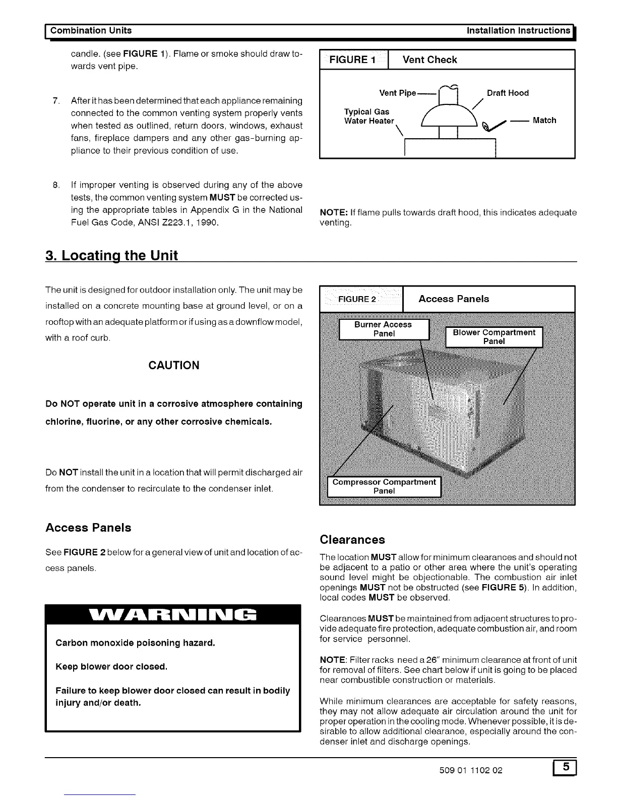
I FIGURE 2
Access Panels
Access Panels
See FIGU RE 2 below for a general view of unit and location of ac-
cess panels.
Carbon monoxide poisoning hazard.
Keep blower door closed.
Failure to keep blower door closed can result in bodily
injury and/or death.
Clearances
The location MUST allow for minimum clearances and should not
be adjacent to a patio or other area where the unit's operating
sound level might be objectionable. The combustion air inlet
openings MUST not be obstructed (see FIGURE 5). In addition,
local codes MUST be observed.
Clearances MUST be maintained from adjacent structures to pro-
vide adequate fire protection, adequate combustion air, and room
for service personnel.
NOTE: Filter racks need a 26" minimum clearance at front of unit
for removal offilters. See chart below if unit is going to be placed
near combustible construction or materials.
While minimum clearances are acceptable for safety reasons,
they may not allow adequate air circulation around the unit for
proper operation in the cooling mode. Whenever possible, it is de-
sirable to allow additional clearance, especially around the con-
denser inlet and discharge openings.
50901 110202 E_]