I Combination Units Installation Instructions
8. Start-up Procedures
Fire and/or explosion hazard.
Do NOT attempt to light the pilot or burner with a match
or flame of any kind.
Failure to follow this warning can result in property
damage, personal injury, and/or death.
Check Before Starting
Check that the blower motor speed terminal block isset for
the correct heating and cooling speeds. Refer to the unit
wiring diagram and tech sheet label and/or Technicallnfor-
mation Manual.
2. Check to see that clean, properly sized air filters are
installed.
3. Replace all service access panels.
Reverse Rotation (Scroll
Compressors Only)
Three phase scroll compressor equipped units CAN run in re-
verse if improperly wired. If the compressor makes an unusually
loud noise, or if high and low side pressures are nearly identical,
this indicates reverse rotation. To correct, reverse any two wires
at line voltage connections ONLY. Do NOT rewire any circuits in-
side the unit to attempt correction of reverse rotation.
Manifold Gas Pressure Adjustment
NOTE: Make adjustment to manifold pressure with burners oper-
ating.
Fire or explosion hazard.
Turn OFF gas at shut off before connecting U-tube ma-
nometer.
Do NOT adjust manifold pressure more than -+0.3 inches
water column to obtain rated input.
Failure to properly set input pressure can result in proper-
ty damage, personal injury and/or death.
1. With gas OFF, Connect U-Tube manometer to tapped
opening on gas valve. Use manometer with a 0 to 12 inches
water column range.
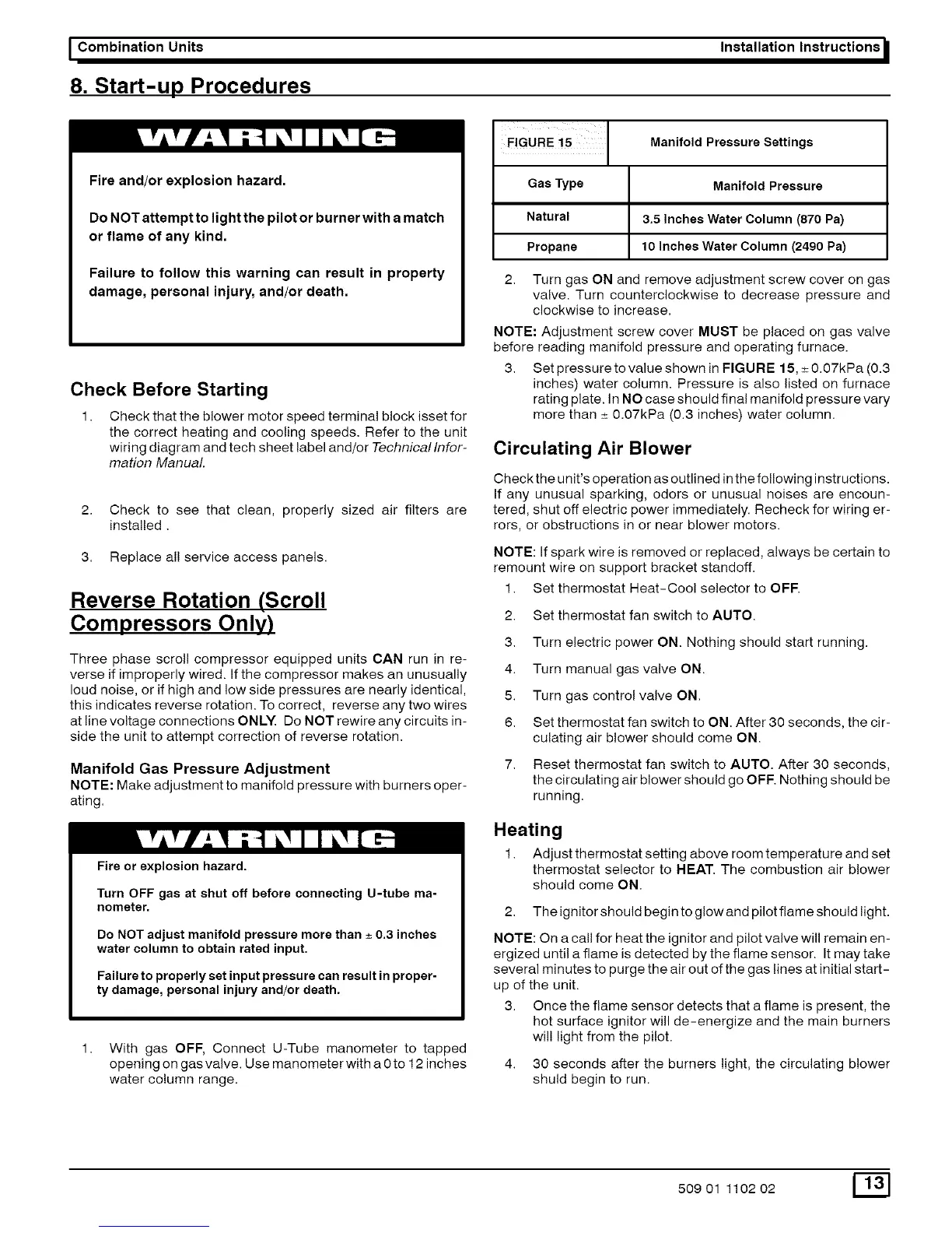
FIGURE 15 Manifold Pressure Settings
Gas Type Manifold Pressure
Natural 3.5 Inches Water Column (870 Pa)
Propane 10 Inches Water Column (2490 Pa)
2. Turn gas ON and remove adjustment screw cover on gas
valve. Turn counterclockwise to decrease pressure and
clockwise to increase.
NOTE: Adjustment screw cover MUST be placed on gas valve
before reading manifold pressure and operating furnace.
3. Set pressure to value shown in FIGURE 15, _+0.07kPa (0.3
inches) water column. Pressure is also listed on furnace
rating plate. In NO case should final manifold pressure vary
more than _+0.07kPa (0.3 inches) water column.
Circulating Air Blower
Check the unit's operation as outlined inthe following instructions.
If any unusual sparking, odors or unusual noises are encoun-
tered, shut off electric power immediately. Recheck for wiring er-
rors, or obstructions in or near blower motors.
NOTE: If spark wire is removed or replaced, always be certain to
remount wire on support bracket standoff.
1. Set thermostat Heat-Cool selector to OFF.
2. Set thermostat fan switch to AUTO.
3. Turn electric power ON. Nothing should start running.
4. Turn manual gas valve ON.
5. Turn gas control valve ON.
6. Set thermostat fan switch to ON. After 30 seconds, the cir-
culating air blower should come ON.
7. Reset thermostat fan switch to AUTO. After 30 seconds,
the circulating air blower should go OFF. Nothing should be
running.
Heating
1. Adjust thermostat setting above room temperature and set
thermostat selector to HEAT. The combustion air blower
should come ON.
2. The ignitor should begin to glow and pilot flame should light.
NOTE: On a call for heat the ignitor and pilot valve will remain en-
ergized until a flame is detected by the flame sensor. It may take
several minutes to purge the air out of the gas lines at initial start-
up of the unit.
3. Once the flame sensor detects that a flame is present, the
hot surface ignitor will de-energize and the main burners
wil! light from the pilot.
4. 30 seconds after the burners light, the circulating blower
shuld begin to run.
50901 110202 _[]