I Installation Instructions
Refer to FIGURE 19 to illustrate location of filter racks and filter
access panel. Filters should be removed and replaced through
this access panel.
Heating Season Checks (Monthly)
Pilot Flame
FIGURE i 6 Pilot Assembly
While the main burner is on, the flame should envelop the upper
part of the flame sensor, as shown in FIGURE 16.
Main Burner Flame
Flames should be stable and solid blue, (dust may cause orange
tips or they may have wisps of yellow, but they MUST not have
solid yellow tips). They should extend directly into the heat ex-
changer tubes and the turbulators should glow orange (after
about five minutes of operation). Main burner flame should be in-
spected monthly.
FIGURE Normal Flame
Turbulator willglow
orange when hot.
Flame should be
stable and solid blue.
Combination Units I
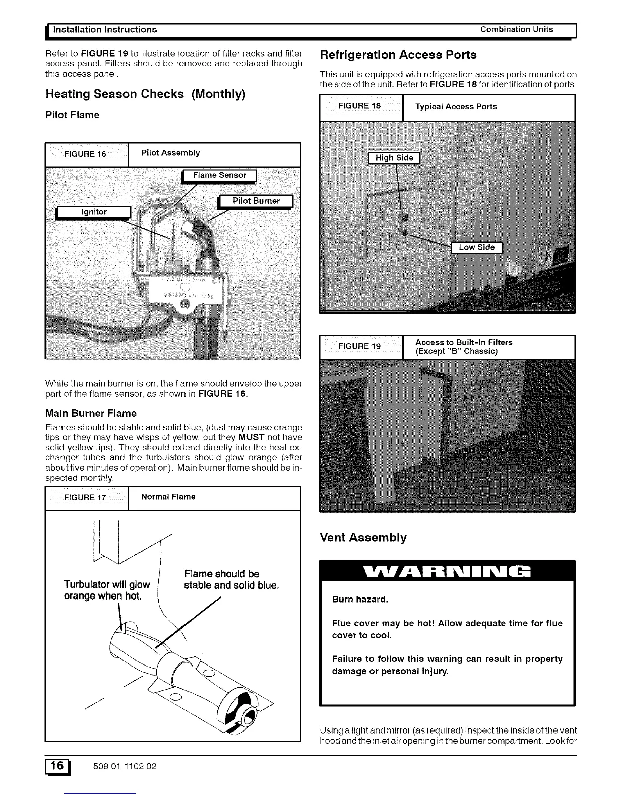
Refrigeration Access Ports
This unit is equipped with refrigeration access ports mounted on
the side of the unit. Refer to FIGURE 18 for identification of ports.
Typical Access Ports
I FIGURE i9 Access to Built-In Filters
(Except "B" Chassic)
Vent Assembly
Burn hazard.
Flue cover may be hott Allow adequate time for flue
cover to cool.
Failure to follow this warning can result in property
damage or personal injury.
Using a light and mirror (as required) inspect the inside of the vent
hood and the inlet air opening in the burner compartment. Look for
E_ 50901 110202