I Installation Instructions
4. Gas Supply and Piping
Combination Units I
Because there are many types of liquefied petroleum (LP) gases,
the term LP as used in this manual refers to propane gas. If you
intend to use any type of LP gas, proper precautions MUST be
used in the handling, piping, and use ofsuch gas. NOTE: In Cana-
da, LP installations MUST be performed by licensed LP installers.
The Rating Plate located on the side panel on the unit contains the
model number, type of gas and gas input rating, and other impor-
tant information.
Fire and/or explosion hazard.
Make certain the unit is equipped to operate on the type
of gas available. Models designated as natural gas are
to be used with natural gas only. Models designated for
use with liquefied petroleum (LP) gas are shipped with
orifices sized for commercially pure propane gas. They
MUST not be used with butane or a mixture of butane
and propane unless properly sized orifices are installed
by a licensed LP installer.
Failure to follow this warning can result in property
damage, personal injury, and/or death.
Gas Pressures
1. Do NOT allow minimum gas supply pressure to fall below
the minimums. Doing so will decrease input to furnace. Re-
fer to FIGURE 7 for gas supply pressures.
2. Gas input MUST NOT exceed rated input shown on rating
plate.
3. Do NOT allow pressures to exceed the maximum limits as
listed in FIGURE 7.
NOTE: If gas supply pressures are not correct, contact your gas
supplier.
Gas Pressures
Natural Gas LP Gas
Minimum
Inlet 4.5"W.C. (1120 Pa) 11" W.C. (2740 Pa)
Pressure
Recom.
Inlet 7" W.C. (1740 Pa) 11" W.C. (2740 Pa)
Pressure
Maximum
Inlet 13"W.0. (3230 Pa) 13"W.C. (3230 Pa)
Pressure
Manifold 3.5" W.C. (870 Pa) 10" W.C. (2490 Pa)
Pressure
Manifold Pressures
Manifold pressures are covered in the startup procedure section.
Refer to Chapter 8, Start-Up Procedures on Page 13.
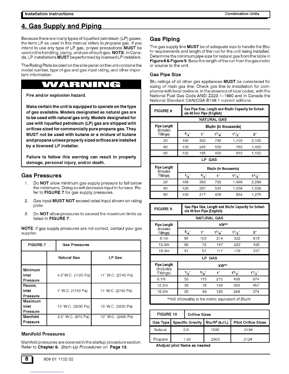
Gas Piping
The gas supply line MUST be of adequate size to handle the Btu/
hr requirements and length of the run for the unit being installed.
Determine the minimum pipe size for natural gas from the table in
Figure 8 & Figure 9. Base the length of the run from the gas meter
or source to the unit.
Gas Pipe Size
Btu ratings of all other gas appliances MUST be considered for
sizing of main gas line. Check gas line to installation for com-
pliance with local codes or, in the absence of local codes, with the
National Fuel Gas Code ANSI Z223.1-1990 and in Canada the
National Standard CAN/CGA B149.1 current editions.
FIGURE 8 GasPipe Size, LengthandBtu/hr Capacityfor Sched-
ule40 Iron Pipe(English)
NATURAL GAS
PipeLength Btu/hr (in thousands)
(Includes
Fittings) 3/4" 1" 11/4" 11/2" 2"
20' 190 350 730 1,100 2,100
40' 130 245 500 760 1,450
60' 105 195 400 610 1,150
LP GAS
PipeLength Btu/hr(inthousands)
(Includes
Fittings) 1/2" 3/4" 1" 11/4" 11/2"
20' 189 393 732 1,496 2,299
40' 129 267 504 1,039 1,559
60' 103 217 409 834 1,275
FIGURE 9
GasPipe Size, LengthandBtu/hr Capacityfor Sched-
ule40 Iron Pipe(English)
NATURAL GAS
PipeLength kW**
(Includes
Fittings) 3/4" 1" 11/4" 11/2" 2"
6.1m 56 103 214 322 615
12.2m 38 72 147 223 425
18.3m 31 57 117 179 337
LP GAS
PipeLength kW**
(includes
Fittings) 1/2" 3/4" 1" 11/4" 11/2"
6.1m 55 115 215 438 574
12.2m 38 78 148 305 457
18.3m 30 64 120 244 374
**kW (Kilowatts) is the metric equivalent of Btu/hr.
FIGURE 10 Orifice Sizes
Gas Type Specific Gravity Btu/ft 3 (k J/L) Pilot Orifice Sizes
Natural 0.6 1000 .018#
Propane 1.53 2500 .012#
#Adjust pilot flame as needed
E_I 50901 110202