I Combination Unite
TABLE 1: Equivalent Orifice Sizes at High Altitudes
(Includes 4% input reduction for each 1,000 ft.
Natural GasManifoldOrifice Size RequiredbyElevation
BTU 0'- 2000' 4500'
INPUT 2000' 4000' 5000' 6000' 7000' 8000' 9000' 10000'
40.000to 44 45 46 47 47 48 48 49
60,00
90,000to 43 44 45 45 46 47 47 48
150,000
LPGas ManifoldOrifice Size Required by Elevation
BTU 0'- 2000' 4500'
INPUT 2000' 4000' 5000' 6000' 7000' 8000' 9000' 10000'
40.000to 55 56 56 56 56 56 56 57
60,000
90,000to 54 55 55 55 55 56 56 56
150,000
* 2-1/2 & 3 Ton with 3 burners.
** 3-1/2 & 4 ton with 4 burners.
Orifices
Installation Instructions
6. Disconnect the pilot tubing from the gas valve.
7. Remove the four screws holding the manifold to the man-
ifold brackets.
8. Carefully remove the manifold with the gas valve attached.
9. Remove the orifices from the manifold with a 7/16" box end
or socket wrench.
10. Check to be sure that the size of each orifice is correct for
the Btu input desired.
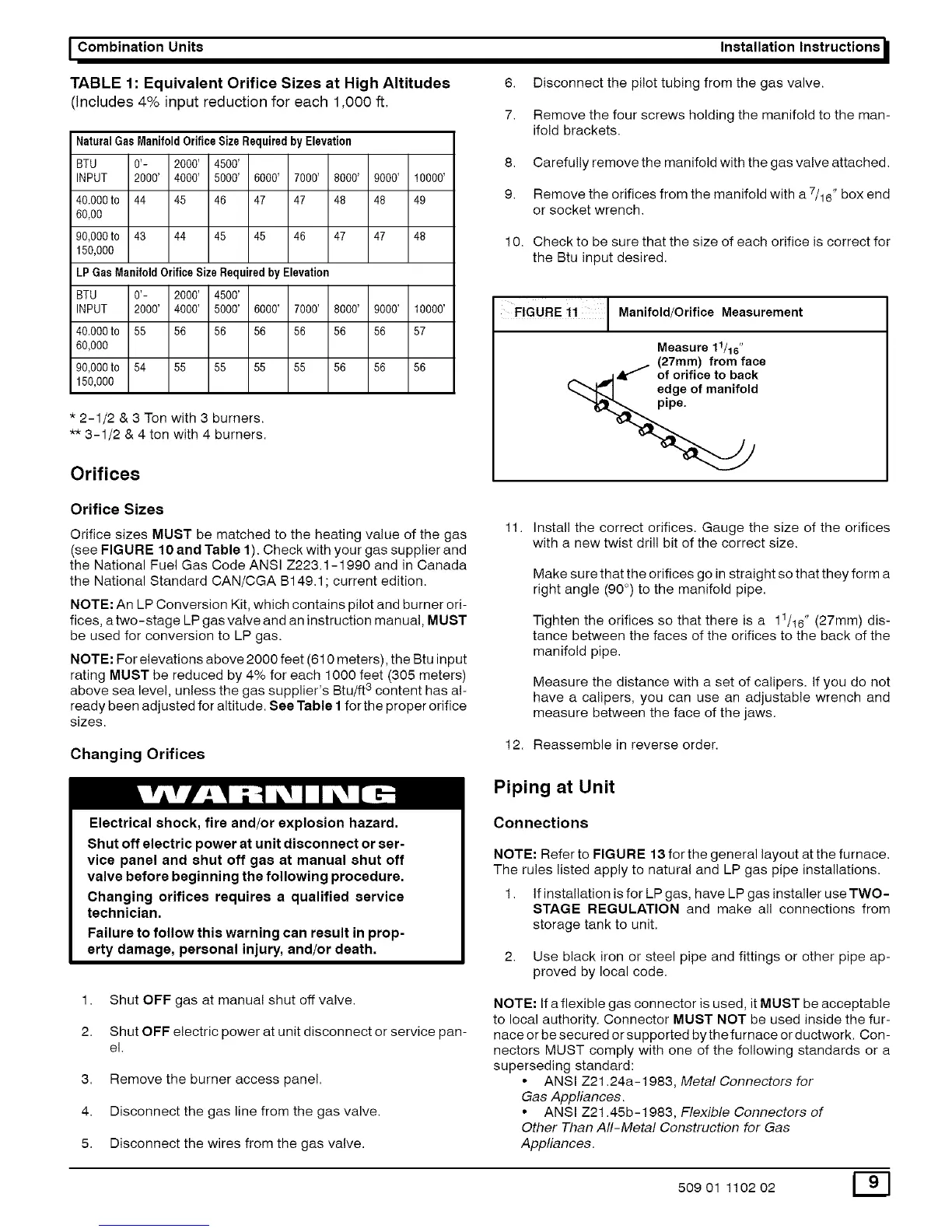
FIGURE ii I Manifold/Orifice Measurement
Measure 11/16"
(27mm) from face
__ .11Ak _ of orifice to back
_,,,,",_J edg I of manifold
Orifice Sizes
Orifice sizes MUST be matched to the heating value of the gas
(see FIGURE 10 and Table 1). Check with your gas supplier and
the National Fuel Gas Code ANSI Z223.1 -1 990 and in Canada
the National Standard CAN/CGA B149.1; current edition.
NOTE: An LP Conversion Kit, which contains pilot and burner ori-
fices, a two-stage LP gas valve and an instruction manual, MUST
be used for conversion to LP gas.
NOTE: For elevations above 2000 feet (610 meters), the Btu input
rating MUST be reduced by 4% for each 1000 feet (305 meters)
, 3
above sea level, unless the gas supplier s Btu/ft content has al-
ready been adjusted for altitude. See Table I for the proper orifice
sizes.
Changing Orifices
Electrical shock, fire and/or explosion hazard.
Shut off electric power at unit disconnect or ser-
vice panel and shut off gas at manual shut off
valve before beginning the following procedure.
Changing orifices requires a qualified service
technician.
Failure to follow this warning can result in prop-
erty damage, personal injury, and/or death.
1. Shut OFF gas at manual shut off valve.
2. Shut OFF electric power at unit disconnect or service pan-
el.
3. Remove the burner access pane!.
4. Disconnect the gas line from the gas valve.
5. Disconnect the wires from the gas valve.
11.
install the correct orifices. Gauge the size of the orifices
with a new twist drill bit of the correct size.
Make sure that the orifices go in straight so that they form a
right angle (90 °) to the manifold pipe.
Tighten the orifices so that there is a 11/16" (27mm) dis-
tance between the faces of the orifices to the back of the
manifold pipe.
Measure the distance with a set of calipers, if you do not
have a calipers, you can use an adjustable wrench and
measure between the face of the jaws.
12. Reassemble in reverse order.
Piping at Unit
Connections
NOTE: Refer to FIGU RE 13 for the general layout at the furnace.
The rules listed apply to natural and LP gas pipe installations.
1. If installation is for LP gas, have LP gas installer use TWO-
STAGE REGULATION and make all connections from
storage tank to unit.
2. Use black iron or steel pipe and fittings or other pipe ap-
proved by local code.
NOTE: If a flexible gas connector is used, it MUST be acceptable
to local authority. Connector MUST NOT be used inside the fur-
nace or be secured or supported bythe furnace or ductwork. Con-
nectors MUST comply with one of the following standards or a
superseding standard:
• ANSI Z21.24a-1983, Metal Connectors for
Gas Appliances.
• ANSI Z21.45b-1983, Flexible Connectors of
Other Than All-Metal Construction for Gas
Appliances.
50901 110202 E_]