TUNNEL MASTER JR MANUAL
System Hardware 10
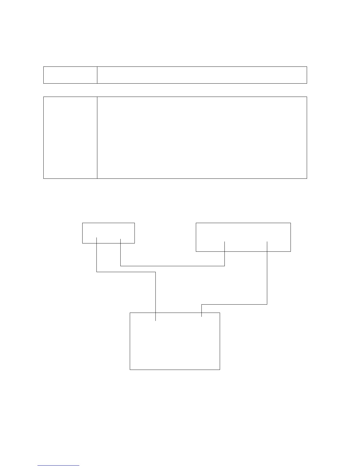
Gate (Electric Eye) Switch Wiring
Gate Switch
Wire Diagram
The following diagram shows how to wire the Gate (electric eye)
switch into the Relay Box.
Important!
The "Gate" switch is the second critical input device to the OEM Relay
Box. It is usually an electric eye system or some type of vehicle
position detector located just before the first piece of wash equipment.
This switch signals the OEM Controller that a vehicle is starting
through the tunnel. All equipment turn on points are measured from
this switch to the particular piece of equipment.
This diagram to the Smart Relay Box starts at the control relay for the
sensing device being used. See the wash equipment provider for
location of this relay.
“
”
OEM Relay Box
Gate
-
Gate
+
24vac Power Source
(Supplied by Other)
NeutralHot
Electric Eye or Other
Sensing Device Relay
N.O.Common
Smart Relay Box
Relay Box
 Loading...