TUNNEL MASTER JR MANUAL
System Hardware 27
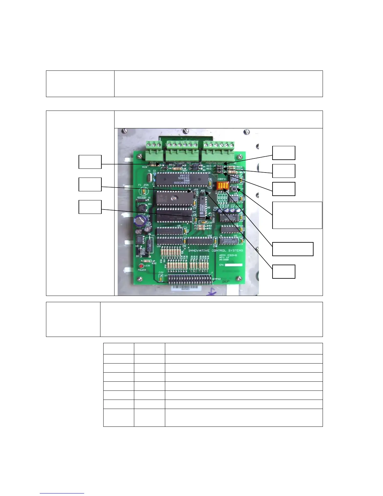
The Entrance Keypad Jumper Settings
Jumper Settings
The following picture and table will explain the location and
purpose of the various jumpers on the Entrance Keypad circuit
board.
The following picture shows the Entrance Keypad circuit board
and location of the various jumpers
Keypad Circuit
Board
Jumper Setting/
Function
These are the jumper functions and their normal settings. By default,
the keypad comes address as 5. There is no reason to change this
unless advised by ICS. If you have two keypads, you should address
the second as address 6.
Jumper Setting Function
J1 ON Reserved Jumper; ALWAYS ON
J2 ON Reserved Jumper; ALWAYS ON
J3 DOWN E-Prom Chip Enable; Jumper Down next to “CE”
J4 ON Ground Jumper
J5 OFF Biasing Resister High (+)
J6 OFF Biasing Resister Low (-)
J7 ON Terminating Resister. Set to ON if it is the first or
last device in the network.
JP1
Dip switch
JP7
JP5
JP6
JP3
JP4
(SW1) Circuit
Board Reset
button
JP2

 Loading...