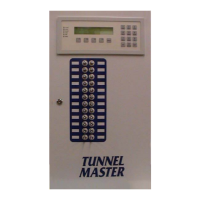
TUNNEL MASTER JR MANUAL
System Hardware 24
The Entrance Keypad Installation
Entrance Keypad Wiring
• There is a terminal block (POWER), located on the keypad circuit board labeled with
24H, 24L and GND, for Hot, Low and Ground, respectfully. Terminations for the 3 –
18AWG wires should be torqued to 20 pound-inches (2.3 n-m.) Overtorquing may
cause enclosure breakage.
• Some OEM Relay boxes may be equipped with a second 24vac transformer, which is to
be used to power the Entrance Keypad. If this second transformer is present the 24vac
terminations must be made as follows from the separate transformer, if there is only one
transformer terminate power from it:
OEM Relay Box Entrance Keypad
24ACH 24H
24ACL 24L
*Gnd Trm GND
*Note: The “Gnd Trm” refers to the grounding lug connector fastened to the lower
right hand corner of the OEM Relay Box
• Electrician must run a single-twisted pair, 24AWG shielded com cable (can be
purchased from ICS) through the above 3/4” conduit from the Relay Box to the
Entrance Keypad.
• There is a terminal block (NETWORK 485), located on the keypad circuit board labeled
with DT+, DT-, and GND, for Data+, Data- and Ground, respectfully. Terminations for
the single-twisted pair com wires should be torqued to 20 pound-inches (2.3 n-m.)
Overtorquing may cause enclosure breakage.
• Com cable terminations must be made as follows:
Relay Box Entrance Keypad
(either connector) (either connector)
TX+ DT+
TX- DT-
GND GND

 Loading...