TUNNEL MASTER JR MANUAL
Wash Configuration 33
The Relay Box Keypad
Introduction
The Relay Box keypad is the primary place from which to program and
configure the wash tunnel. If your facility has two relay boxes, one of
them will serve as the primary input relay box. From this screen you
can:
• Setup and configure the wash tunnel outputs and services
• View car count and some sales information
• Print vehicle count and sales information, if optional report
printer is installed.
• Some equipment diagnostics occur at the OEM Relay Box
• Manually process cars and apply services.
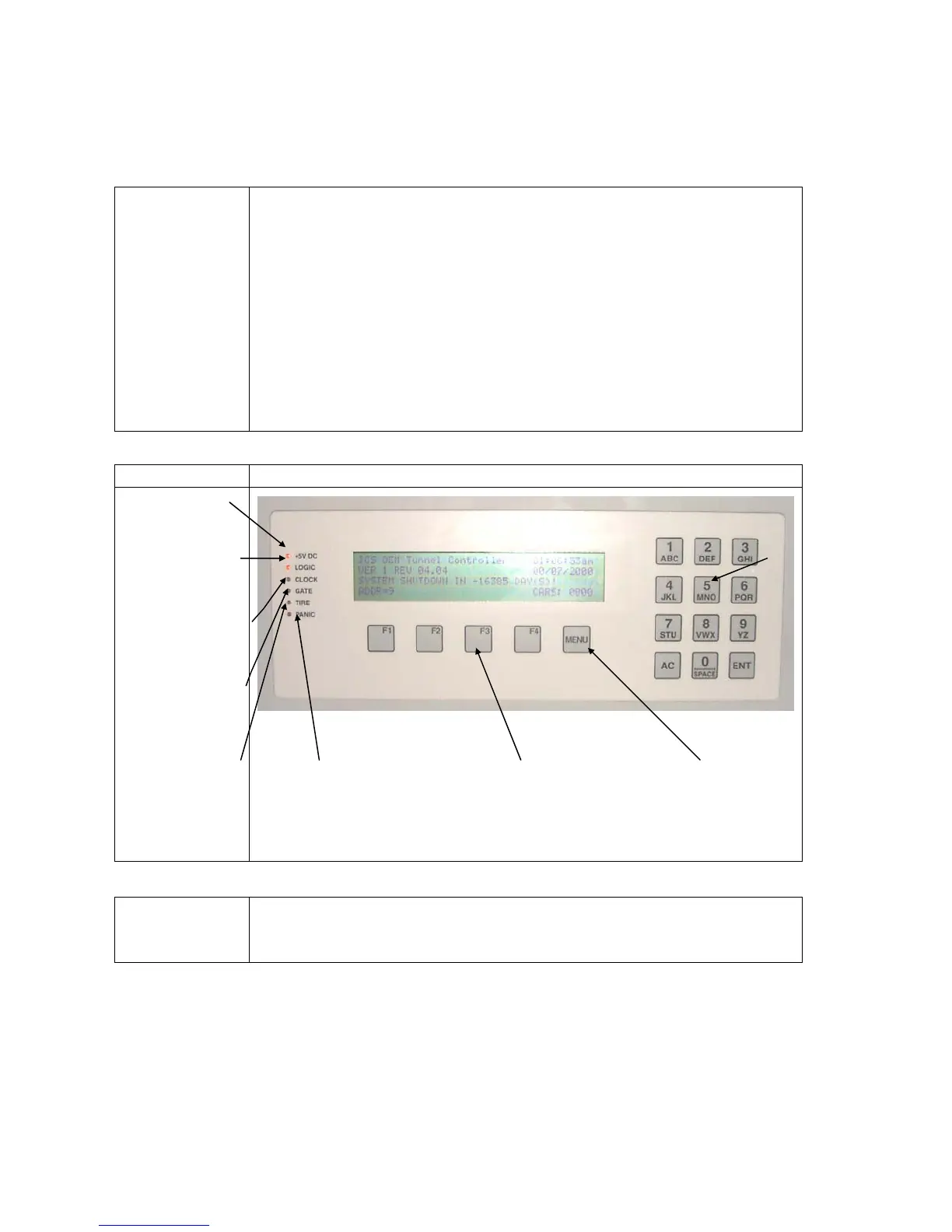
Picture
This is a picture of the Keypad.
Note
In order to utilize the full functionality of the Tunnel Master Jr.
Controller, it is very important that the electrician adhere to the wiring
instructions provided with the Relay Box.
+5 Volt indicator light,
indicates power good
to input terminal
Gate switch indicator
light when on, indicates
gate switch (electric eye)
is on and sensing.
Logic Light, indicates
communications active
between Opto and
Input Terminal
Clock indicator light
When blinking, indicates
operation of pulse switch
on conveyor.
Tire switch indicator
light. When on,
indicates tire switch is
on and sensing.
Panic condition indicator
light , When on, indicates
panic circuit is activated
Function buttons, (F1 –
F4) Used when
programming system.
Menu button. Used
when accessing menu
options.
Numeric keys.
Used when
entering data and
programming
 Loading...