MACH+ heat recovery units— User and installer manual
© Ideal Clima-Page 16 / 20
8.11 ELECTRICAL CONNECTION
The electrical connection, 230V +T; 50Hz, must be carried out according to the wiring diagram set out in
Chapter 4.2 of this Manual.
The most appropriate upstream switch of the line is the MGT-C10. The power line shall have the same or greater
characteristics as the fror-3g1, 5 cable.
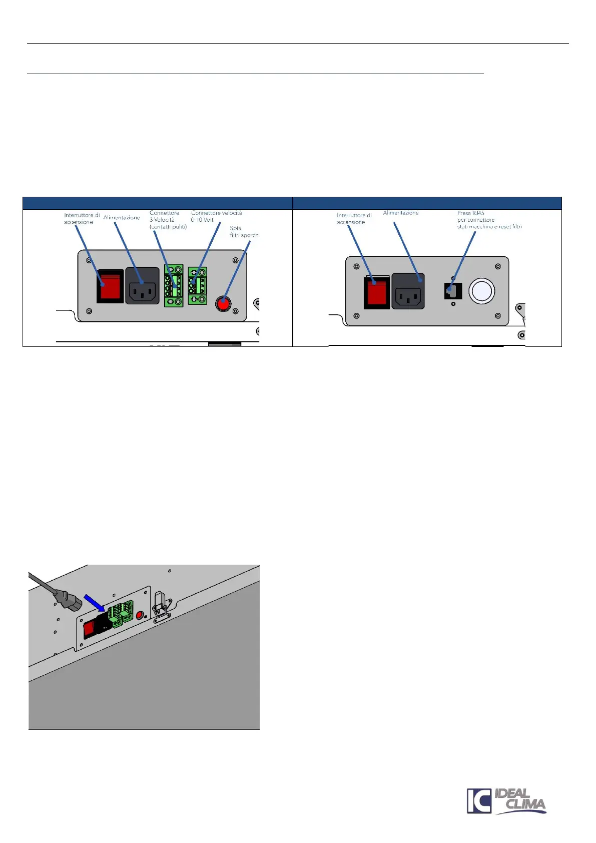
PANEL ON BOARD MACHINE:
The on-board panel and its contacts change depending on the version and in particular according to the
presence of automatic freecoling adjustment:
MANUAL FREE-COOLING MACH+ WIRING
Remote Control Linea:
Connect the common and speed selector as indicated in diagram 4.2.1 to the terminal block placed on the
connection electrical panel. Clean contacts are mandatory. Otherwise, interpose relays.
Signal line clogged filters:
The warning light, placed on the electrical panel of connection, does not require additional connection.
To remote the signal connect a second indicator light, (at 230V, not supplied) in parallel to the existing one.
Line reset alarm filters
There is no need to set up any electrical connection for filter reset. Once the filters are cleaned or replaced,
the indicator lights will turn off automatically (the differential pressure switch returns to the rest position)
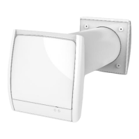
Supply Line:
Insert the VDE power plug into the connector next to the ignition switch, on the electrical connection panel.
Cable and plug are supplied.